|
.JPG)
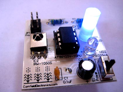
Bare Board
|
 |
Step 02:
Here is the bare board, before soldering anything onto it. This is the Top side of the board.
We will insert ALL of the parts into the Top side of the board
(and solder the parts on the Bottom side).
|
|

First part to solder: R2
|
|
Step 03:
The first part we will solder in is R2, which is a 220 Ohm resistor.
Color code: [Red][Red][Black][Black][Brown]
|
|
.JPG)
Bend leads of R2
|
|
Step 04:
Before inserting any resistor into the board, you must bend both of their leads as shown.
|
|
.jpg)
Insert R2 into board
|
|
Step 05:
Insert R2 into the board, as shown.
|
|
.jpg)
Resistors can be inserted either way (they're not polarized)
|
|
Step 06:
With resistors you do not need to worry about what direction it is placed in to the board.
(Resistors are not polarized.)
|
|
.JPG)
R2 inserted, leads bent out in a "V"
|
|
Step 07:
Push R2 all of the way into the board, and then bend the wires like a 'V' to hold the component in place while soldering.
|
|
.jpg)
Now it's time to solder
|
|
Step 08:
It is now time to solder R2. First one lead, then the other.
|
|
.jpg)
R2 being soldered
|
|
Step 09:
The metal areas on the board with holes are called "pads". Each lead is inserted into its own pad. Each lead is soldered to its pad.
|
|
.jpg)
R2 soldered in place
|
|
Step 10:
Take a moment to admire your handiwork.
|
|
.jpg)
Cut leads of R2
|
|
Step 11:
Now that all leads of the component are soldered, cut each lead short. Use the tip of the wire cutter, with the flat side of the wire cutter facing the board.
IMPORTANT: Always hold (or cover) the lead while you cut it, otherwise it may fly into your eye!
|
|
.jpg)
Close up of cutting a lead short
|
|
Step 12:
You can see here a close-up of cutting a lead short.
IMPORTANT: Always hold (or cover) the lead while you cut it, otherwise it may fly into your eye!
|
|
2.png)
Leads cut short
|
|
Step 13:
After cutting the leads short, it should look something like this. There is very little lead sticking out from each solder connection.
The main idea is that no excess wire can bend and make a connection we don't want. (If there is a connection we don't want, our project won't work!)
|
|

Resistor R1
|
|
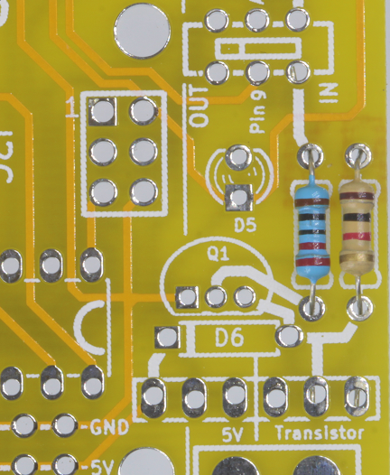
Step 14:
The next part to solder in is R1, which is a 1K Ohm resistor.
Color code: [Brown][Black][Red][Gold]
|
|
R1 placement
|
|
Step 15:
The photo shows where you put R1.
Following the same procedure as Step 04 through Step 13, solder in R1.
( Note that this photo is an updated one. The rest of the pictures, below, will not show this exact same resistor ).
|
|
-001.png)
Microcontroller socket orientation
|
|
Step 16:
It is now time for the microcontroller socket. Note that there is a little notch on one end.
|
|
-002.png)
Bare Board
|
|
Step 17:
You need to match the notch in the socket with the white half-circle marking on the printed circuit board.
IMPORTANT: The socket should very easily slide into place -- do not force it.
If any of the pins are bent so that they don't all line up, straighten them out gently with your fingers before inserting the socket.
|
|
-003.png)
Bend and solder two corners of microcontroller socket
|
|
Step 18:
Bend the pins at two opposite corners out to hold the socket in place while soldering.
Solder these two corners first.
|
|
.JPG)
Solder all microcontroller socket pins
|
|
Step 19:
Now you are ready to solder all of the pins of the microcontroller socket.
|
|
.jpg)
Place the 6-pin header
|
|
Step 20:
Place the 6-pin header into the board as shown.
IMPORTANT: Be sure that the long pins are facing out from the board.
|
|
-005.png)
Solder the 6-pin header
|
|
Step 21:
These thick pins are very good at transferring heat, so you can save your table from getting burned by placing a coin underneath.
To make it easier, solder one pin of this header on the top of the board first.
This will hold the component in place while soldering the other pins from the bottom.
|
|
-007.png)
Three ceramic 0.1uF capacitors
|
|
Step 22:
Now we'll solder the three little ceramic 0.1uF capacitors.
These components are not affected by what direction you place them in. (They are not polarized.)
Solder these in, one at a time:
insert, bend leads out in a "V", solder, cut leads short.
C1 is used as part of the communication circuit between the microcontroller and the serial line.
C2 is used to smooth out the power that comes from the barrel jack.
C4 is to smooth out the USB power.
|
|
.jpg)
Ceramic resonator
|
|
Step 23:
The component with 3 leads is called a ceramic resonator.
It resonates at 16 MHz and tells the microcontroller exactly how fast to clock through its code.
It does not matter in which direction you insert the ceramic resonator (it is not polarized).
Solder it in: insert, bend the two outside leads in a "V", solder, cut leads short
REMEMBER to cover the leads when you cut them to keep your eyes safe!
|
|
-008.png)
Microcontroller orientation
|
|
Step 24:
Next let's orient the most expensive component on the board.
The microcontroller is an ATmega328 by Atmel.
It is very important that you place it into its socket in the correct direction.
IMPORTANT: Make sure that the notch at one end of the microcontroller lines up with the notch in the socket
(and the white half circle on the board).
IMPORTANT:The pins of the microcontroller need to be all lined up, and parallel,
so that when lightly placed on top of its socket, each pin of the chip rests in its own hole in the socket.
DON'T push it in, yet...
|
|
-010.png)
Close-up showing the microcontroller's notch
|
|
Step 25:
This close-up photo shows all three markings matching up altogether on one end.
|
|
.JPG)
Push microcontroller into socket
|
|
Step 26:
Now that the microcontroller is oriented properly, and each of the pins are aligned in their holes,
push the microcontroller into its socket using two thumbs.
It takes a significant amount of pressure to push the chip into the socket.
IMPORTANT:As you push the microcontroller into its socket, be sure that all of the pins are actually going into their holes.
If a pin looks like it is bending, that means that the pins weren't all straight and parallel.
So, using a small screwdriver (or toothpick), pry the microcontroller out of its socket, straighten the pins, and try again.
|
|
.jpg)
C3 position
|
|
Step 27:
The photo shows one of the electrolytic capacitors for this project.
They have much more capacity than the small capacitors.
The small ceramic capacitors can respond quickly to higher frequency changes in power consumption.
These larger electrolytic capacitors can smooth out bigger slower changes in power.
IMPORTANT: Electrolytic capacitors need to be placed in the circuit board in the correct direction.
The longer lead goes in the whole marked with the plus sign (+). (Electrolytic capacitors are polarized.)
|
|
-010.png)
Inserting C3
|
|
Step 28:
Here is a close-up photo, showing the long lead going into the pad marked with "+".
Also note that the negative side of the electrolytic capacitor is marked with a "-" (in the big gray stripe).
Solder in C3: insert, bend leads out in a "V", solder, cut leads short.
|
|
-012.png)
Solder C5
|
|
Step 29:
Solder in C5, which (like C3) is an electrolytic capacitor,
so it matters which way you insert it: long lead goes into the pad marked with "+".
Insert, bend leads out in a "V", solder, cut leads short.
|
|
.jpg)
Resistor array placement
|
|
Step 30:
Now it's time to place the resistor array.
This resistor array contains all of the resistors used for the four neighboring LEDs,
as well as the reset button "pull up".
We will talk about the "pull up" later when we talk about the reset button.
|
|
-013.png)
Resistor array orientation
|
|
Step 31:
It is very IMPORTANT that the diamond is placed at the same end as the solder pad with the square around it.
Once inserted, bend the two outside leads outward in a "V", solder all 6 of its leads, and cut them short
(while remembering to cover the leads while cutting!).
|
|
-014.png)
LED Orientation
|
|
Step 32:
Now we can insert the Red LED.
IMPORTANT: All LEDs must be inserted into the board in the correct direction.
The long lead is "+". Also, the plastic lip of the LED isn't actually a circle -- the "-" side of the LED has a flat edge.
For this board, the pad for "+" of each LED is a square pad.
|
|
.jpg)
All four LEDs soldered in place
|
|
Step 33:
Solder the four LEDs:
Insert (long lead in the square pad), bend leads out in a "V", solder, cut short.
|
|
-015.png)
Diode D3
|
|
Step 34:
Diodes are one-way valves for electrons. Current only flows one way.
All diodes have a "+" side and a "-" side
(including, as you already saw, LEDs, which are a special kind of diode: a Light Emitting Diode).
For regular diodes, the "-" side is marked by a band (the color is unimportant).
For this diode, D3, the band is gray.
Bend the leads of the diode, and insert into the pads for D3, with the "-" side (with the band) in the square pad.
Solder D3:
Insert (""-" lead in the square pad), bend leads out in a "V", solder, cut short.
|
|
.jpg)
Diode D6
|
|
Step 35:
D6 is soldered in the same as for D3 in the last step
("-" lead in the square pad).
It is easy to slip while using the knife.
If that happens, you can hurt the board,
and more importantly, you can cut yourself.
Please don't do that.
|
|
.jpg)
Cut trace jumper
|
|
Step 36:
Using a razor, carefully cut the trace between the pads, as shown in the photo.
|
|
.jpg)
Insert power switch
|
|
Step 37:
Insert the power switch.
|
|
-019.png)
Bend leads of power switch, and solder
|
|
Step 38:
Bend the leads of the power switch out, and solder all of the leads to their pads.
|
|
.JPG)
Bend leads of LM7805
|
|
Step 39:
The LM7805 is a popular analog regulator chip.
It converts a large range of input Voltages (between 6V and 12V) into a regulated output Voltage of 5V.
This 5V is used to power the ATmega328 microcontroller in the U-Do-It-Duino.
Before inserting the LM7805 into the board, bend its leads down, as shown in this photo.
|
|
.JPG)
Insert and solder LM7805
|
|
Step 40:
Insert the LM7805 into its pads as shown in the photo.
Bend the two outside leads out into a "V", solder all three leads, and cut the leads short.
|
|
.JPG)
41
|
|
Step 41:
41.
|
|
.JPG)
42
|
|
Step 42:
42.
|
|
.JPG)
43
|
|
Step 43:
43.
|
|
.JPG)
44
|
|
Step 44:
44.
|
|
-1.jpg)
45
|
|
Step 45:
45.
|
|
-020.png)
46
|
|
Step 46:
46.
|
|
.JPG)
47
|
|
Step 47:
47.
|
|
.JPG)
48
|
|
Step 48:
48.
|
|
.jpg)
49
|
|
Step 49:
49.
|
|
.jpg)
50
|
|
Step 50:
50.
|
|
.jpg)
51
|
|
Step 51:
51.
|
|
.jpg)
52
|
|
Step 52:
52.
|
|
.JPG)
53
|
|
Step 53:
53.
|
|
.jpg)
54
|
|
Step 54:
54.
|
|
.jpg)
55
|
|
Step 55:
55.
|
|
.JPG)
56
|
|
Step 56:
56.
|
|
.JPG)
57
|
|
Step 57:
57.
|
|
.JPG)
58
|
|
Step 58:
58.
|
|
-2.JPG)
59
|
|
Step 59:
59.
|
|
.JPG)
60
|
|
Step 60:
60.
|
|
.JPG)
61
|
|
Step 61:
61.
|
|
Completed U-Do-It-Duino board
|
|
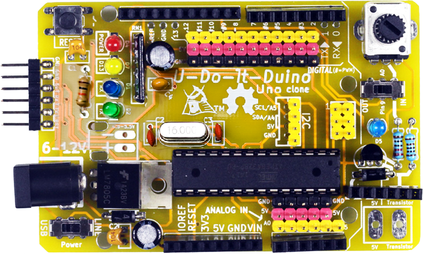
Step 62:
Completed U-Do-It-Duino board.
(Click on the image to enlarge.)
|
|
USB-Serial Cable connected properly
|
|
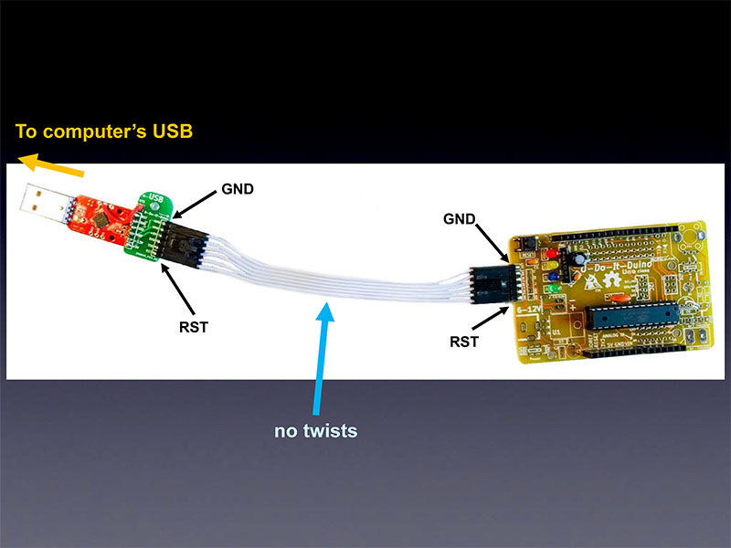
Step 63:
63.
|
|
Debugging is fun!!
|
|
Step 64:
Debugging Suggestions:
- Is the battery inserted the correct way? (The smooth side with the "+" should face towards you, and away from the PCB.)
- As noted above, the CR2032 battery included with the kit may be weak or dead. So, try replacing it.
- Are all of the solder connections good?
(Check against the five qualities of good solder connections in step 7. If any are not so good, then simply re-do them.)
Even if they all look good, you can try "re-flowing" each connection by:
- touching your cleaned soldering iron tip to a solder connection
- add a tiny bit of solder (about 1/16" or 1.5mm)
- hold the hot soldering iron tip there for about 1 second to let the solder flow nicely
Do the above for every solder connection. (It actually goes really fast!)
- Are all of the parts placed into the PCB in the correct place?
- Are all of the parts placed in their proper orientation (for polarized parts)?
If you are having trouble, please feel free to email me with questions!
You can also email me (high-resolution, in-focus photos of both the top and bottom of the board for me to inspect.
My email address:
mitch AT CornfieldElectronics DOT com
|
|
|