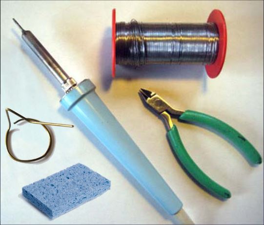
Tools you need
|
 |
Step 01:
These are the tools you will need:
- Soldering Iron (35W or less)
- Solder wire (recommendation: 60/40 rosin core, 0.031" diameter or less)
- Soldering Iron Stand (a bent wire coat hangar works fine)
- cellulose kitchen sponge (not plastic)
- small Wire Cutters
For recommendations on tools, and a really nice tutorial on how to solder, please see:
My Tutorial on "How to Solder"
|
|
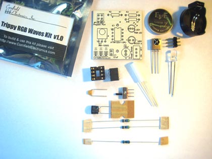
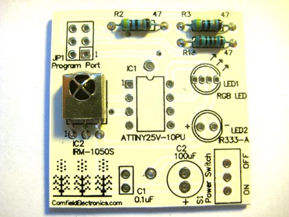
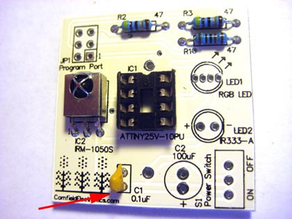
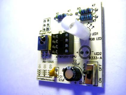
Kit contents
|
|
Step 02:
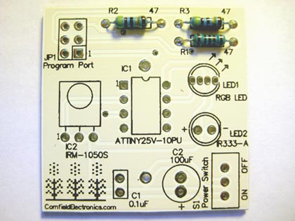
Lay out all of the parts in front of you. A complete list of parts is available at:
Trippy RGB Waves Kit Bill of Materials.
All of these parts are available at mouser.com, digikey.com, jameco.com.
mouser.com,
digikey.com.
jameco.com.
Suggested parts numbers are given in the parts list.
A schematic for this kit is available at:
Trippy RGB Waves Kit schematic.
Note: The CR2032 coin-cell battery included with the kit may be weak or dead.
These coin cells are available at any drug store or hardware store, as well as at electronics stores.
|
|
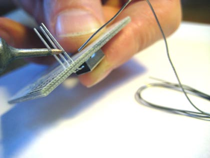
Lead bending
|
|
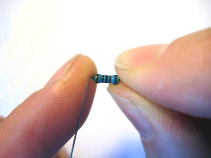
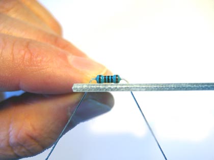
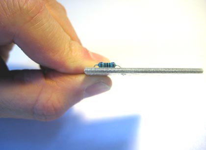
Step 03:
We will start with resistor R1.
The colored bands indicate the value of the resistor.
1K Ohms in this case.
The colored bands for R1 can be either:
brown, black, red, and gold (4-bands)
or
brown, black, black, black, and brown (5-bands)
The wires of all resistors should be bent down on both sides of the part, as shown.
Another word for wires that come out of electronic parts is "leads"
(pronounced "leeds").
|
|
Insertion of R1 |
|
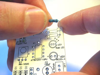
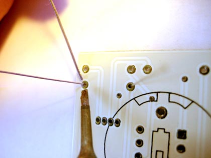
Step 04:
Push the leads from R1 into the pads for R1 on the PCB.
"PCB" stands for Printed Circuit Board, and is the white board that all
of the electronic parts are soldered on to.
"Pads" are the metal areas on the PCB, usually with a hole in the middle,
where the parts will be soldered into.
NOTE: It does not matter which lead of a resistor goes into which pad.
This is because resistors are "non-polarized".
|
|
Bend leads out before soldering
|
|
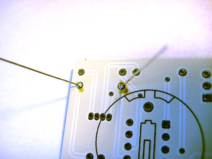
Step 05:
After placing R1 through it’s pads on the PCB, bend its leads outward a little, as shown.
This allows the PCB to be turned over without R1 falling out while we solder it in place.
|
|
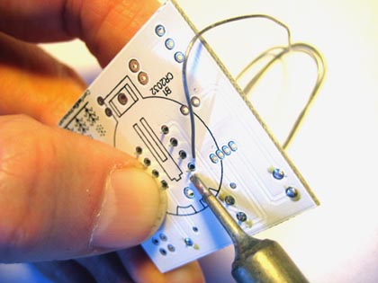
Soldering
|
|
Step 06:
Soldering is done by following these steps:
- Clean the solder iron tip by wiping it on the wet sponge
- Touch the clean solder iron tip to both the lead and the pad and let it heat up everything for about 1 second
- Add about 1/8" (about 3mm) of solder under the solder iron tip - the solder should melt and flow nicely around the lead and pad
- Keep the solder iron tip on the lead and pad for about another second, until the solder is nicely flowed all around the pad and lead
- Lift up the solder iron tip from the pad and lead.
NOTE: Please see my really nice
Tutorial on "How to Solder" for more details on how to solder like a pro!
|
|
Good solder connections
|
|
Step 07:
Here you can see R1 soldered into place on the PCB.
You can tell a nice solder connection by these five qualities:
- The solder flowed nicely around the pad and lead -- no lumps
- The surface of the solder is smooth -- not lumpy
- The solder totallycovers the entire pad -- you can't see any bare pad
- The solder forms a little mountain -- not flat
- There is no solder blob connecting your soldered pad to any other pad
There is a lot of leeway between not enough solder (soldered connection is flat, or you can see some bare pad)
and too much solder (a huge blob that shorts out to another pad).
This is why soldering is easy!
|
|
Lead clipping |
|
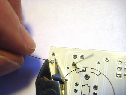
Step 08:
Clip both of the leads of R1 so that they are somewhat flush with the PCB surface.
It is not important that the cut be absolutely flush with the PCB.
The main thing is that there is not enough of the lead left over to bend over and
short out to another pad.
IMPORTANT: when clipping leads, always hold the lead with one hand while clipping with the other.
This keeps the lead from flying somewhere unwanted -- such as into your eye! -- or shorting out some pads somewhere.
|
|
R1 soldered in place
|
|
Step 09:
You can see here the leads of R1 clipped to an appropriate length.
There is no way they can bend over to short anything out.
|
|
All resistors soldered in place
|
|
Step 10:
Repeat steps 3 through 9 for the rest of the resistors: R2 and R3.
The picture shows where each resistor goes.
R2 and R3 are both the same. They are both 47 Ohms.
The colored bands for R2 and R3 can be either:
yellow, violet, black, and gold (4-bands)
or
yellow, violet, black, gold, and brown (5-bands)
Remember, resistors are non-polarized, so it does not matter which way they go in their pads.
|
|
Bending leads of IC2
|
|
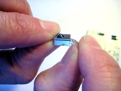
Step 11:
Bend the leads for IC2 (the IR detector) at 90 degrees, as shown, to prepare it for insertion into the PCB.
FYI: "IR" means "Infra Red", which is an invisible color of light (our eyeballs don't respond to IR).
|
|
Insertion of IC2
|
|
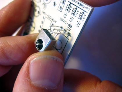
Step 12:
Insert IC2 into the PCB as shown in the photo.
|
|
Soldering IC2
|
|
Step 13:
Solder IC2 into place.
Since one hand will be holding the IR detector and PCB, and the other hand will be holding the
solder iron, we do not have a third hand to hold the solder.
So, you can use a small coil of solder to hold the solder in the correct position,
as shown in the photo (bend the solder so that it points down a little bit).
If you don’t hold the IR detector in place when you turn the PCB upside down to solder it,
it will fall out.
So you will need to hold it onto the PCB with one finger, as shown in the photo.
Make sure you don’t touch the leads of IC2 on the top of the PCB while soldering them
(or you will feel the pain!).
|
|
IC2 soldered in place
|
|
Step 14:
Here is how IC2 looks when it is soldered in place.
|
|
Placement of the socket for IC1
|
|
Step 15:
Insert the socket for IC1 (the microcontroller) into its pads.
IMPORTANT: Notice that there is a notch on the black drawing for IC1 that matches with the notch
on the socket - make sure these line up when you insert it into the PCB.
IMPORTANT: Make sure the pins of the IC1 socket are straight, and slide easily into their 8 pads.
These pins bend easily, so if one or more are crooked, gently straighten them with your fingers before inserting the socket into place.
|
|
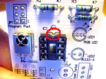
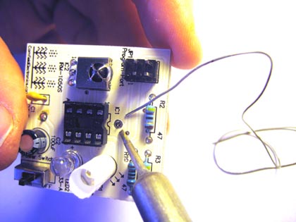
Soldering the corners of the socket for IC1
|
|
Step 16:
Since one hand will be holding the socket and PCB, and the other hand will be holding
the solder iron, we do not have a third hand to hold the solder.
So, similarly to when you soldered IC2, you can coil some solder to hold the solder
in the correct position, as shown in the photo
(remember to bend the solder so that it points down a little bit).
Hold the socket onto the PCB with one finger while you solder, as shown in the photo.
And remember to make sure you don’t touch the metal on the top of the PCB
for the pin you are soldering on the bottom (since it will get hot!).
After soldering the pin in one corner of the socket, solder the pin in the opposite corner.
PLEASE SEE THE NEXT TWO PHOTOS.
|
|
Two opposite corners of IC1 soldered
|
|
Step 17:
Here you can see two opposite corners of IC1 soldered in place.
PLEASE SEE NEXT PHOTO.
|
|
All pins of IC1 soldered
|
|
Step 18:
Now that you have soldered the pins in two opposite corners, the socket won't fall out of the PCB, and you can
solder the remaining 6 pins into the PCB the normal way.
NOTE: After soldering these 8 pins into the board, there is no way the pins can bend and make a connection you don't want,
so there is no need to cut them short. (I recommend not cutting them.)
NOTE: You may notice that in my photos (and perhaps on your board, too),
that there are brown spots on the board after soldering.
This is not a bad thing. The board is not burned.
That is the rosin (the chemical in the solder wire) that melted, and then hardened
again. And on the white PCB you can see that its color is brown. It is not a problem.
|
|
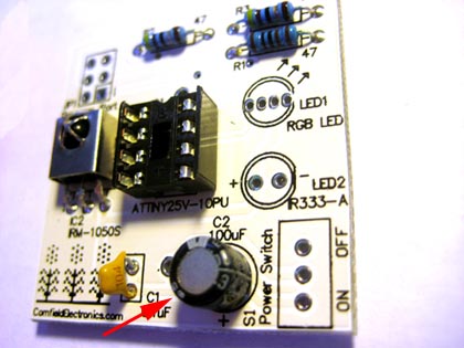
C1 soldered in place
|
|
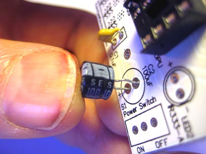
Step 19:
Repeat steps 4 through 9 to solder in C1, as shown.
(C1 is not polar, so it does not matter which way it is inserted).
|
|
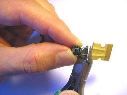
Cut tape from C2
|
|
Step 20:
If it came with tape, cut off the tape from C2.
FYI: The tape is used in automatic assembly machines, for mass production purposes.
|
|
Proper placement of C2
|
|
Step 21:
Since C2 is polarized, it does matter which way it is inserted into its pads.
Insert C2 into the pads as shown.
The negative lead is denoted with the small ’-’ sign.
The positive lead is the longer lead (before you cut it, of course).
|
|
C2 soldered in place
|
|
Step 22:
Here you can see C2 properly soldered into place.
|
|
S1 soldered in place
|
|
Step 23:
Repeat steps 4 through 9 to solder into place the three leads of S1, as shown.
You may need to coil the solder as a "third hand".
IMPORTANT: Please clip the three leads after soldering them since they are long enough
to short out pads if you don't cut them short.
|
|
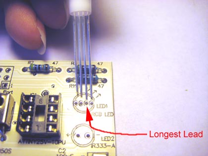
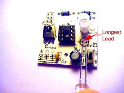
Proper placement of RGB LED placement
|
|
Step 24:
Insert the RGB LED into its pads as shown --
please note the longest lead goes into the second pad from the right.
NOTE: Before soldering this into place, gently wiggle it back and forth until it is inserted as far into the PCB
as it will go without forcing it. Then it is ready for soldering all 4 of its leads.
(It won't push all of the way into the PCB.)
Repeat steps 4 though 9 to solder all 4 of the leads of the RGB LED into place.
FYI: "RGB" stands for Red-Green-Blue. If you mix different amounts of Red and Green and Blue light together
you can get almost any color you want. This is how this project creates all of its cool, trippy colors!
|
|
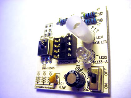
RGB LED soldered in place
|
|
Step 25:
Here you can see the RGB LED properly soldered into place.
|
|
Proper placement of the IR emitter
|
|
Step 26:
Insert the IR emitter into its pads as shown --
please note the longest lead goes into the pad marked ’+’.
Repeat steps 4 though 9 to solder the IR emitter into place.
|
|
IR emitter soldered in place |
|
Step 27:
Here you can see the IR emitter properly soldered into place.
|
|
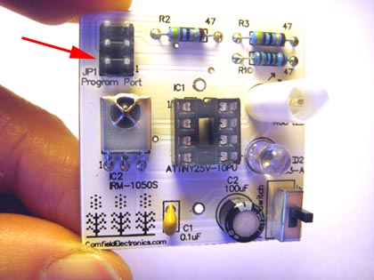
JP1 soldered in place
|
|
Step 28:
THIS PART IS OPTIONAL
It is only used if you would like to re-program the microcontroller.
(To do this you will need an AVR programmer.)
If you want to solder in this part:
Repeat steps 4 though 9 to solder JP1 into place.
IMPORTANT: The short leads go into the PCB!
(If the short leads are inserted into the PCB, JP1 can be placed into the PCB in two ways, and it does not matter which way it is placed.)
Similarly to when you soldered in the socket for IC1,
start by soldering in two opposite corners,
being careful to not touch the metal that you are soldering.
After soldering the two corners, then you can solder the remaining 4 leads in the normal way.
There is no need to clip the leads of JP1 after soldering them. (I recommend not cuttin them.)
|
|
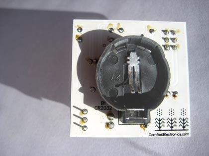
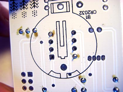
Proper placement of the battery holder
|
|
Step 29:
Position the battery holder on the bottom of the PCB as shown so its two leads go into their pads.
IMPORTANT: Unlike all of the other parts in this kit, this part is inserted into the bottom of the PCB.
IMPORTANT: This part is polarized -- be sure to orient it as shown in the photo.
|
|
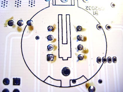
Soldering the battery holder
|
|
Step 30:
Repeat steps 4 though 9 to solder the two leads of the battery holder into place.
You may need to coil the solder as a "third hand".
|
|
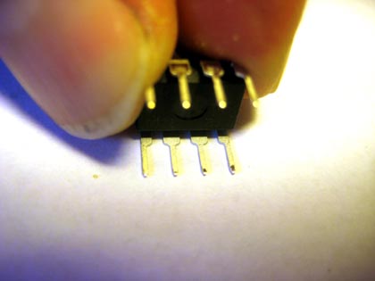
Bending the pins of the microcontroller
|
|
Step 31:
When chips are new, the leads are often bent outward.
Ideally, we want the leads of the chips to point straight down,
with all leads parallel to each other.
By lightly pushing downward on a table you can make all of the leads parallel.
FYI: "Chip" is another word for Integrated Circuit. (In this case, the chip is a microcontroller.)
|
|
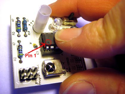
Insertion of the microcontroller
|
|
Step 32:
Place IC1 into its socket.
IMPORTANT: Pin 1 of the chip is marked by a little black dot in one corner.
Place the chip into the socket so that pin 1 is just to the left of the little notch on the socket and PCB,
as shown in the photo.
IMPORTANT: Only push the chip into its socket
if all of its pins are aligned so that each fits into its holes in the socket.
If they are not aligned, when you push the chip down, a pin may bend underneath the chip, and not go into its hole in the socket.
If the pins are not aligned, again gently push one side, and then the other against the table, as in step 32.
Once the pins are all aligned, push the chip into its socket.
|
|
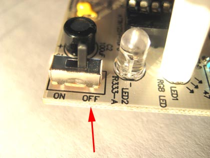
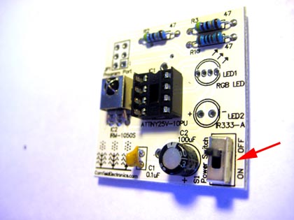
Power switched off
|
|
Step 33:
Turn the power off, by sliding the switch as shown.
|
|
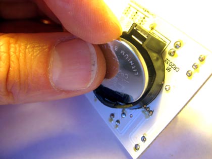
Proper insertion of the battery
|
|
Step 34:
Insert the CR2032 coin cell battery into its holder as shown.
The battery has one side that is smooth and is marked with a "+". This "+" marking faces towards you, away from the PCB.
Note: The CR2032 coin-cell battery included with the kit may be weak or dead.
These coin cells are available at any drug store or hardware store, as well as at electronics stores.
|
|
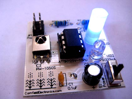
Power on and enjoy!
|
|
Step 35:
If everything is OK, when you switch on the power
you should see the RGB LED light up and go through a changing color sequence
(which starts off with Red, then changes to Green, then Blue, and then other colors).
Then, wave your hand over the PCB, and you should see
the color sequence start over again from the beginning
(starting with Red, then changing to Green, then Blue, and then other colors).
If the RGB LED does not light up, turn off the power immediately, and debug.
See Step 37 for debugging suggestions.
|
|
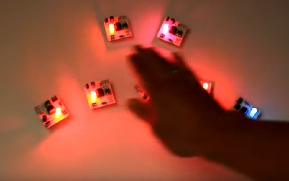
Waving hand over several Trippy RGB Waves kits
|
|
Step 36:
If you have several Trippy RGB Waves kits, you can lay them out in front of you, all with the power on,
and they will all independently be going through their sequence of trippy, cool, pretty colors.
But wave your hand over them, and all of them change their colors and follow your hand
to get the real trippy action going! Waves of colors follow your hand.
Here is a video of several Trippy RGB Waves doing their thing.
|
|
Debugging is fun!!
|
|
Step 37:
Debugging Suggestions:
- Is the battery inserted the correct way? (The smooth side with the "+" should face towards you, and away from the PCB.)
- As noted above, the CR2032 battery included with the kit may be weak or dead. So, try replacing it.
- Are all of the solder connections good?
(Check against the five qualities of good solder connections in step 7. If any are not so good, then simply re-do them.)
Even if they all look good, you can try "re-flowing" each connection by:
- touching your cleaned soldering iron tip to a solder connection
- add a tiny bit of solder (about 1/16" or 1.5mm)
- hold the hot soldering iron tip there for about 1 second to let the solder flow nicely
Do the above for every solder connection. (It actually goes really fast!)
- Are all of the parts placed into the PCB in the correct place?
- Are all of the parts placed in their proper orientation (for polarized parts)?
If you are having trouble, please feel free to email me with questions!
You can also email me (high-resolution, in-focus photos of both the top and bottom of the board for me to inspect.
My email address:
mitch AT CornfieldElectronics DOT com
|
|
|