Tools you need |
 |
Step 01:
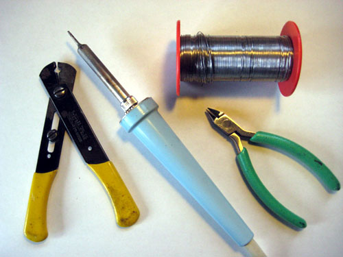
These are the tools you will need:
- Solder Iron
- Solder
- Wire Cutters
- Wire Strippers
For recommendations on these tools, Ladyada’s website is a really nice resource:
http://ladyada.net/make/minipov3/make.html
I have written a comic book that anyone can use to learn to solder --
with the total beginner in mind! It's free and fun to download and read:
Soldering Is Easy!
Ladyada’s website also has some nice soldering tutorials:
http://ladyada.net/learn/soldering/thm.html
|
|
Kit contents |
|
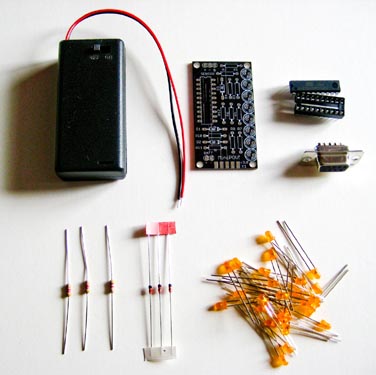
Step 02:
Lay out all of the parts before you. A complete list of parts is available at:
LED Cube Kit Bill of Materials,
which includes suggested parts numbers.
All of these parts are available at
mouser.com,
jameco.com,
and
adafruit.com.
Note that the PCB (Printed Circuit Board, which is the board that all the parts are soldered to) is for the MiniPOV3 kit, by Ladyada. We will only solder to some of the pads of the PCB ("pads" are the silver circles and rectangles, which are where we solder the parts to the PCB)
Note: all wires coming out of the parts, no matter what they look like, are called "leads" (pronounced, leedz).
A schematic for this kit is available at:
LEDcube Kit schematic.
|
|
Solder parts to the PCB
(click for larger image)
|
|
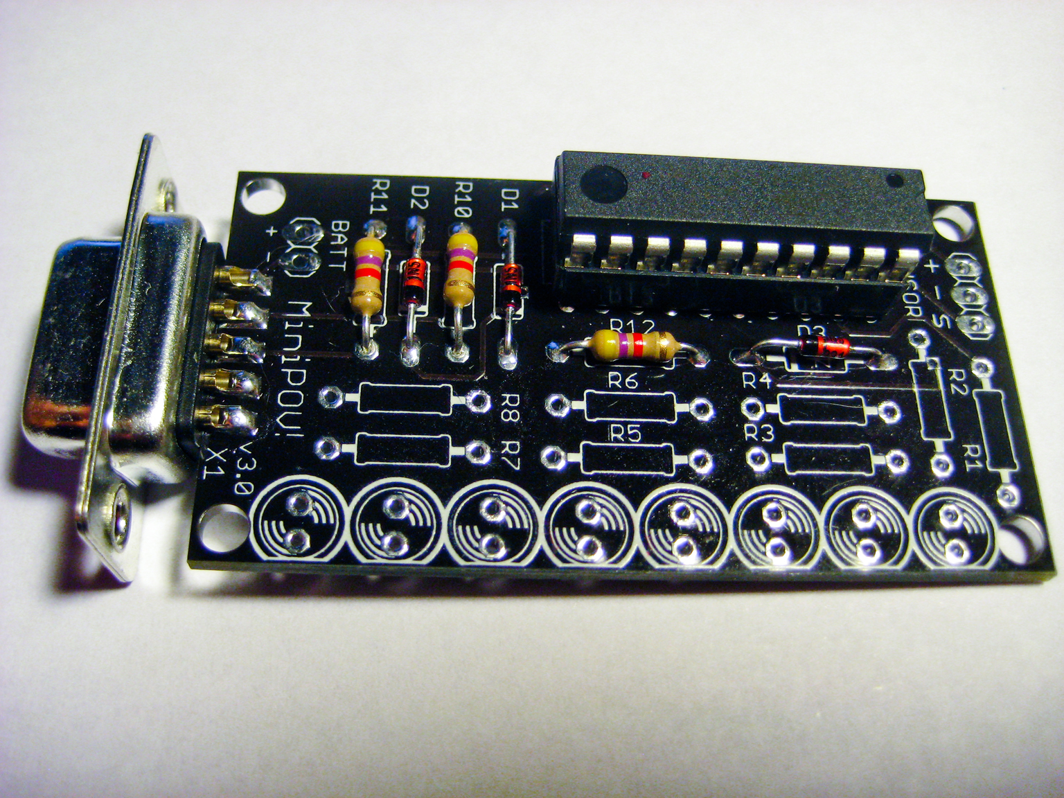
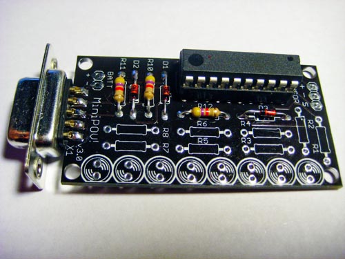
Step 03:
Solder the following parts to the PCB:
- R10, R11, R12
- D1, D2, D3
- the microdcontroller socket
- the serial port connector
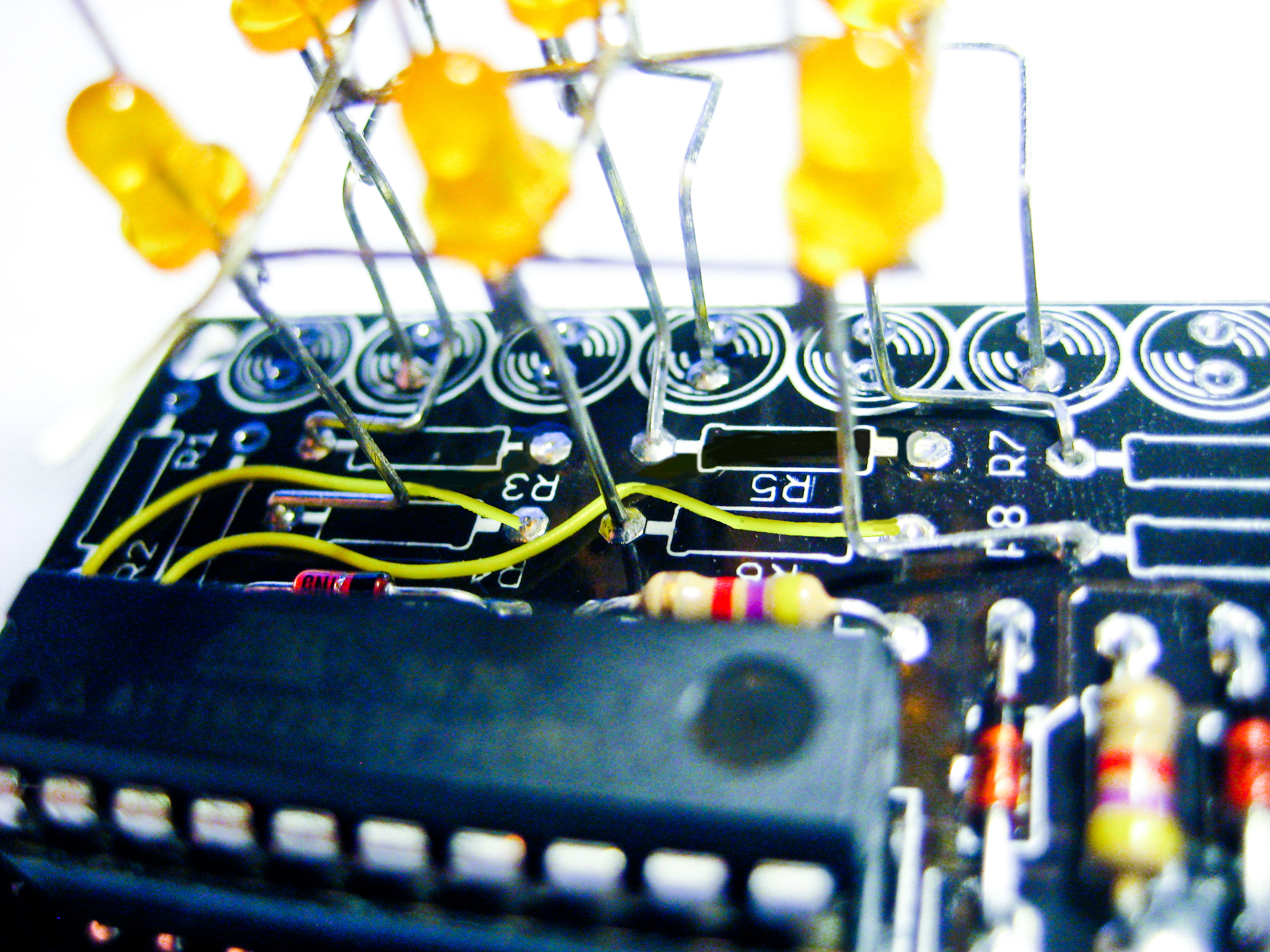
For this project we will only solder three resistors to the PCB: R10, R11, and R12 (as in the photo). Resistors can be oriented in the PCB in either direction. All three of these resistors are: yellow-violet-red-gold. It does not matter which way the resistors are oriented on the PCB.
Make sure that the black bars on the diodes match the printed white bars on the PCB for D1, D2, D3 (oriented as in the photo).
Make sure that the notch on the microcontroller socket matches the notch on the printed drawing for the socket on the PCB. Solder all 20 pins to their pads, on the bottom of the PCB.
Push the microcontroller into its socket, making sure that the notch on the chip matches the notch on the socket (and the PCB).
Push the serial port onto the edge of the PCB so that the 9 pins are centered on the 9 rectangular pads (5 on top of the PCB, 4 on the bottom of the PCB). Solder all 9 pins, making sure that for each one the solder surrounds the pin and covers the entire pad, and making sure that there are no solder blobs that connect any of the pads.
(For detailed instructions on soldering these parts to the PCB, please see the steps for these parts in the
MiniPOV3 kit assembly instructions.)
When you are finished with this step, your board should look like the photo.
|
|
LED Planes Drawing -- we need 3 planes just like this |
|
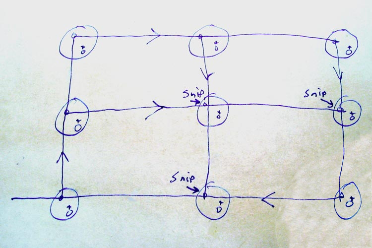
Step 04:
The drawing on the left represents one plane of 9 LEDs. The cube we will create consists of three identical planes.
In the next several steps (Step 5 through Step 32) we will actually solder the plane together, but this section gives a preview and an overview of what we will be doing.
Note: All LEDs have two leads: the long lead is the anode (which is "+" or "plus"), and the short lead is the cathode (which is "-" or "minus").
To begin, all 9 LEDs in the drawing have their two leads pointing straight up at you from the plane. These 9 LEDs fit into the 9 holes of the supplied jig. Notice on the drawing that the two leads for all LEDs are at a 45 degree angle, with the "-" lead for all LEDS facing towards the upper-left, and "+" lead for all LEDS facing towards the bottom-right of the jig.
When making a plane, we will leave all of the "+" leads alone, and we will solder all of the "-" leads together. All but three of the "-" leads will be bent down horizontally (these three will remain pointing up until we snip them short, after soldering). To prevent any of the "+" and "-" leads from shorting, it is important that the LEDs are inserted into the jig with their "+" and "-" leads at 45 degree angles (as stated in the previous paragraph).
On the drawing, the lines with arrows indicate the direction that you are supposed to bend down a "-" lead -- these bent leads will reach all the way across 3 LEDs in the plane. We will perform one bend at a time, and solder this bent
"-" lead to the other two LEDs' "-" leads that this bent lead touches (being careful that no "+" leads touch any "-" leads).
After bending and soldering the 6 "-" leads (the ones with arrows in the drawing), all 9 of the LEDs' "-" leads will be connected together as one common-cathode for the plane. To complete the plane, we will snip off the three "-" leads that are sticking straight up. The excess "-" leads that will stick out of the sides are cut off as we go along (except for the one short piece of wire sticking out a little from the bottom-left LED, as shown in the drawing -- this will be the common-cathode connection for the plane).
When the plane is finished, all 9 of the "+" leads should still be untouched (sticking straight up), without anything soldered to them, and with none of them touching any of the "-" leads.
So, let's now solder together a plane of 9 LEDs!
|
|
Insert LEDs into jig |
|
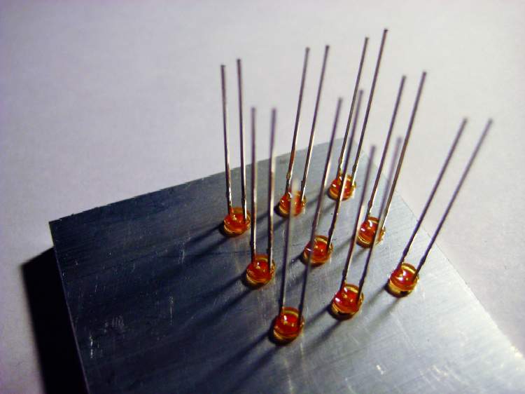
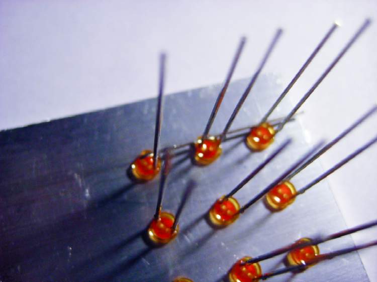
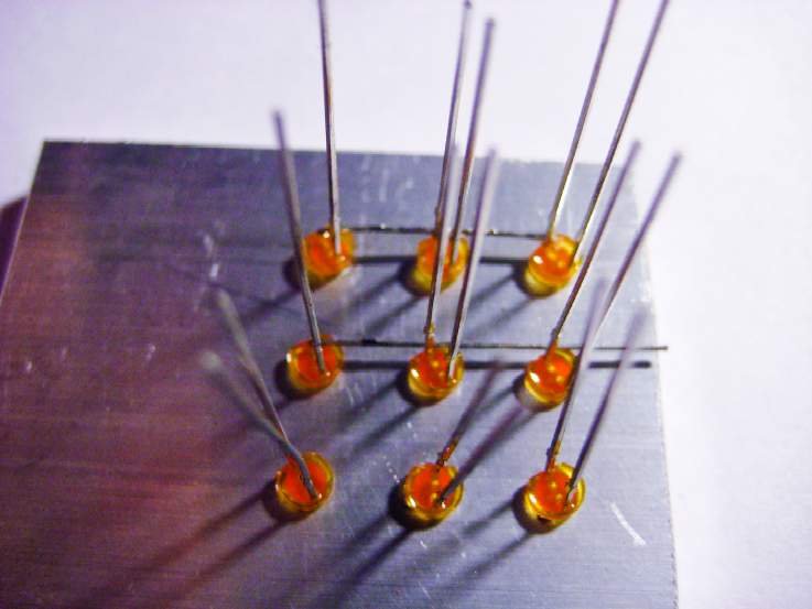
Step 05:
Before doing this step, please read Step 4, above, for important info.
Insert the 9 LEDs into the supplied jig. Make sure that the two leads of each LED are all at a 45 degree angle, with the "-" lead (the short lead) of all LEDs facing the upper-left of the jig, as shown in the photo.
|
|
Bend over the first lead |
|
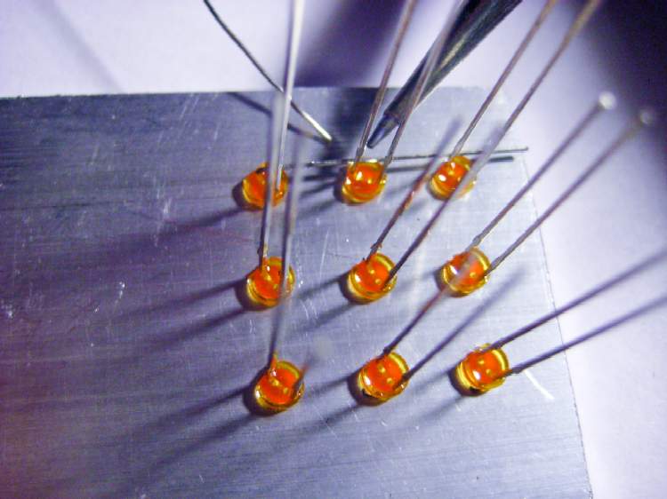
Step 06:
Bend over the "-" lead of the LED shown in the upper-left corner of the photo.
This step can be a bit tricky, as the LEDs will rotate in their holes while you bend the lead over. Please make sure that after bending the lead that all of the leads of the LEDs are at 45 degree angles, with their "-" leads towards the upper-left.
|
|
Solder the first "-" lead to the middle "-" lead of this row |
|
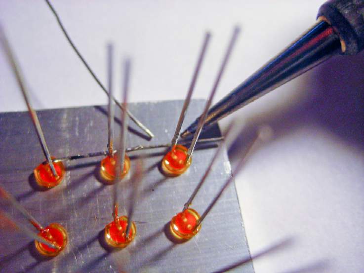
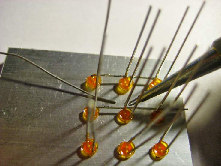
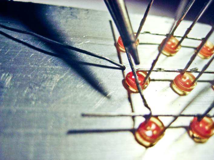
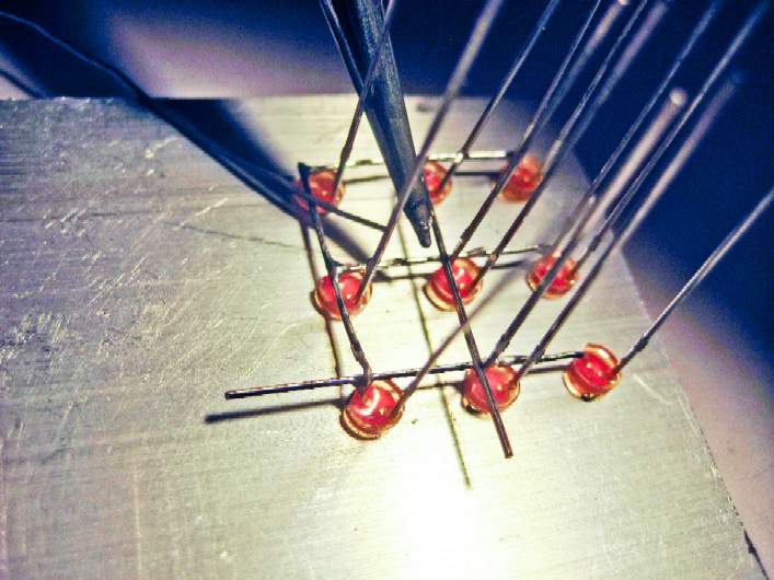
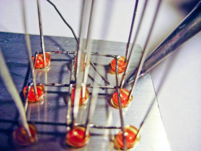
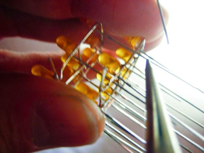
Step 07:
Solder the bent lead to the "-" lead (remember, that's the short lead!) of the middle LED of the row at the top of the jig. Make sure to keep the LED's leads at a 45 degree angle, with the "-" lead facing towards the upper-left of the jig.
|
|
Solder the first "-" lead to the right "-" lead of this row |
|
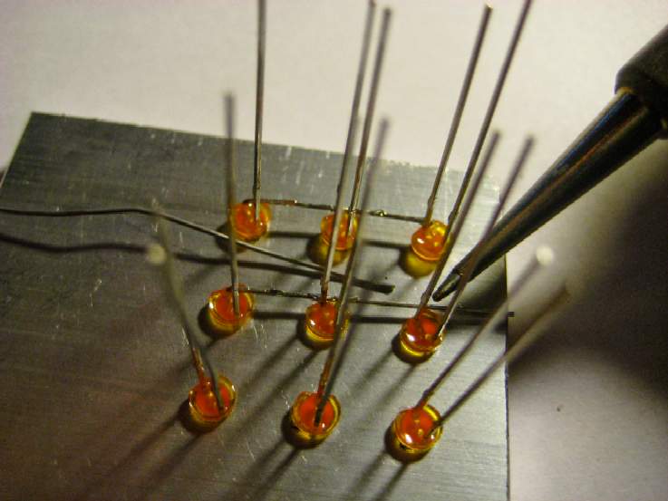
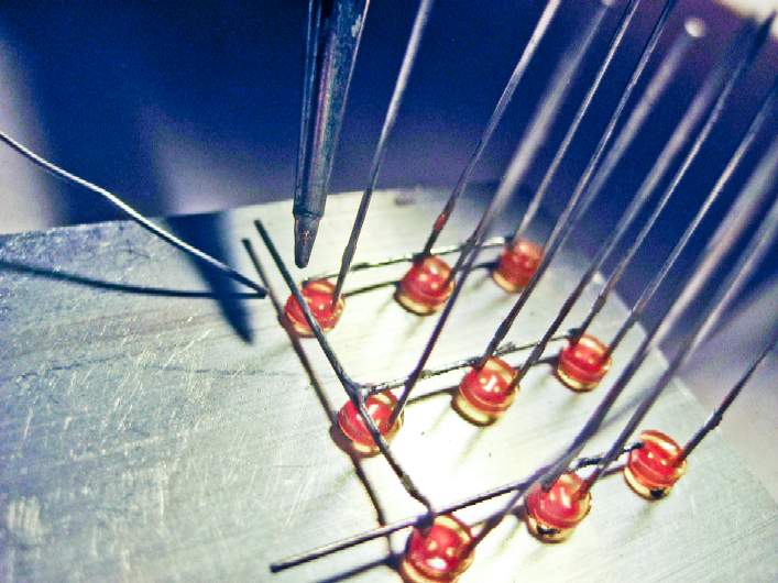
Step 08:
Solder the bent lead to the "-" lead (remember, that's the short lead!) of the right-most LED of the row at the top of the jig. Make sure to keep the LED's leads at a 45 degree angle, with the "-" lead facing towards the upper-left of the jig.
|
|
Clip the excess "-" lead |
|
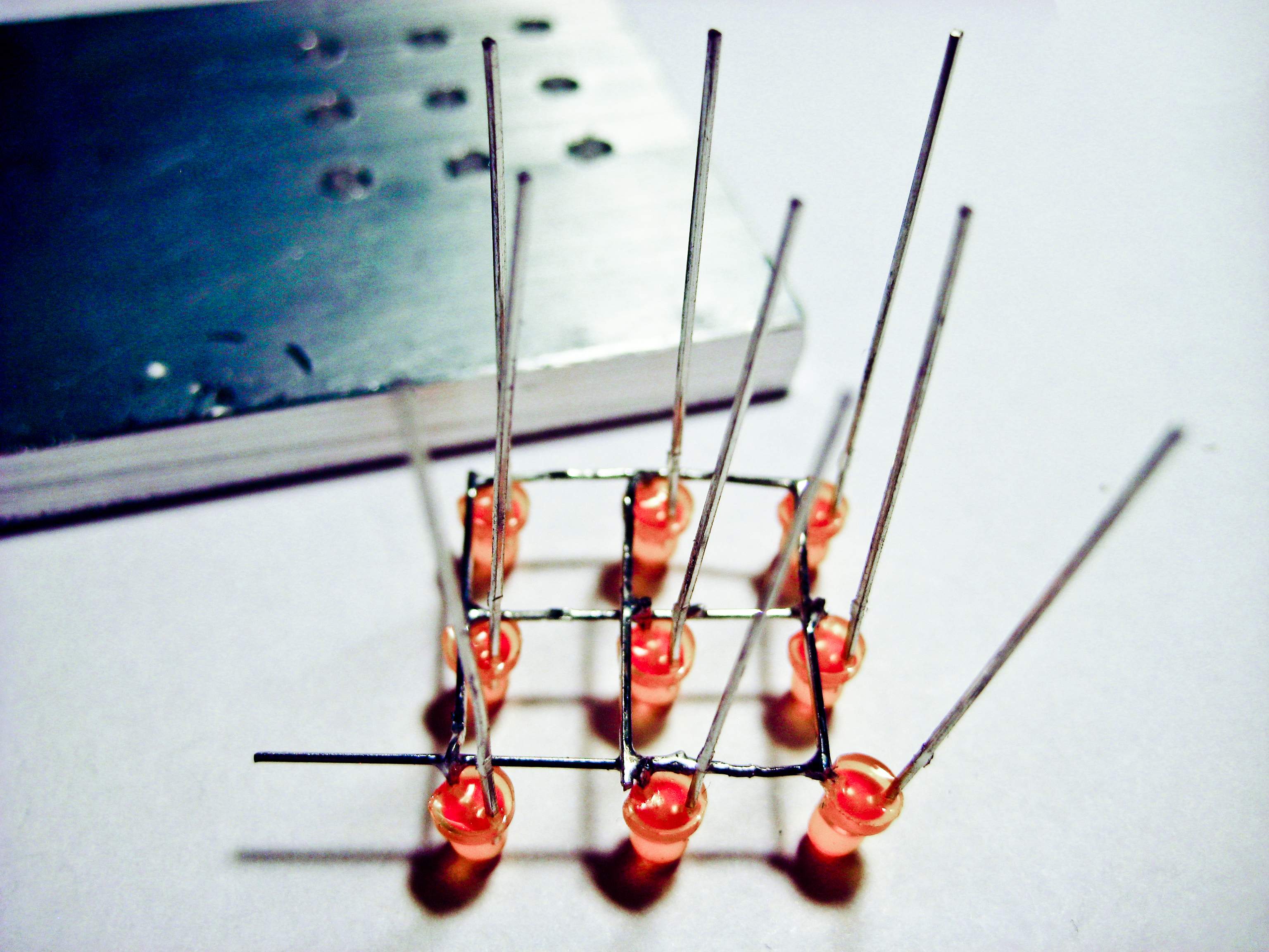
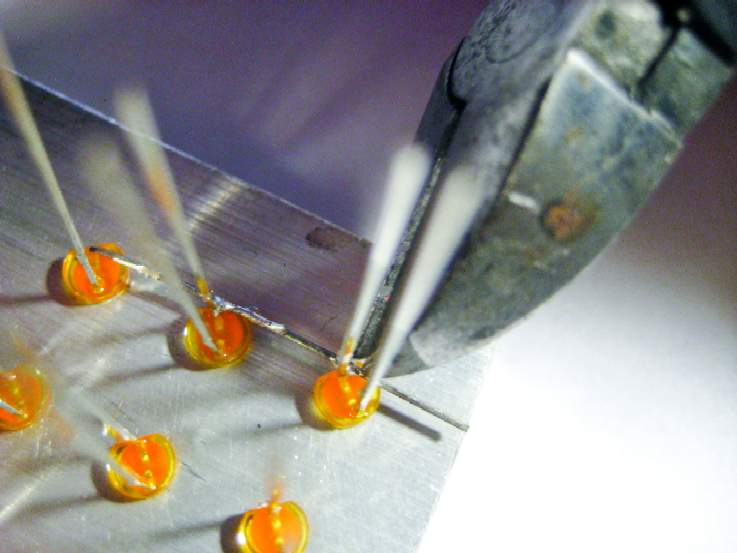
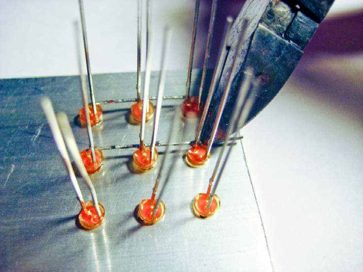
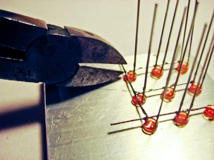
Step 09:
Clip the excess lead that is sticking out from the side, as shown in the photo. Be careful not to snip the "+" lead -- all "+" leads must remain full length, sticking straight up.
|
|
Bend over the second lead |
|
Step 10:
Bend over the "-" lead of the left-most LED in the middle row as shown in the photo.
This step is definitely a bit tricky, as the LEDs will rotate in their holes while you bend the lead over. Again, please make sure that after bending the lead that all of the leads of the LEDs are at 45 degree angles, with their "-" leads towards the upper-left in the jig.
|
|
Solder the second "-" lead to the middle "-" lead of this row |
|
Step 11:
Solder this bent lead to the "-" lead (remember, that's the short lead!) of the middle LED of the middle row. Again, make sure to keep the LED's leads at a 45 degree angle.
|
|
Solder the second "-" lead to the right "-" lead of this row |
|
Step 12:
Solder the bent lead to the "-" lead (the short lead) of the right-most LED of the middle row. Yet again, make sure to keep the LED's leads at a 45 degree angle.
|
|
Clip the excess "-" lead |
|
Step 13:
Clip the excess lead sticking out from the side, as shown in the photo. Be careful not to snip the "+" lead -- all "+" leads must remain full length, sticking straight up.
|
|
Bend over the third lead |
|
Step 14:
Bend over the "-" lead of the LED shown in the bottom-right corner of the photo.
Again, this step is a bit tricky, as the LEDs will rotate in their holes while you bend the lead over. Please make sure that after bending the lead that all of the leads of the LEDs are at 45 degree angles, with their "-" leads towards the upper-left in the jig.
|
|
Solder the third "-" lead to the middle "-" lead of this row |
|
Step 15:
Solder this bent lead to the "-" lead (remember, that's the short lead!) of the middle LED of the bottom row. Again, make sure to keep the LED's leads at a 45 degree angle.
|
|
Solder the third "-" lead to the left "-" lead of this row |
|
Step 16:
Solder the bent lead to the "-" lead (the short lead) of the left-most LED of the bottom row. Yet again, make sure to keep the LED's leads at a 45 degree angle.
Do not clip the excess lead sticking out of the side. This is the common-cathode conection for this plane.
|
|
Bend over the fourth lead |
|
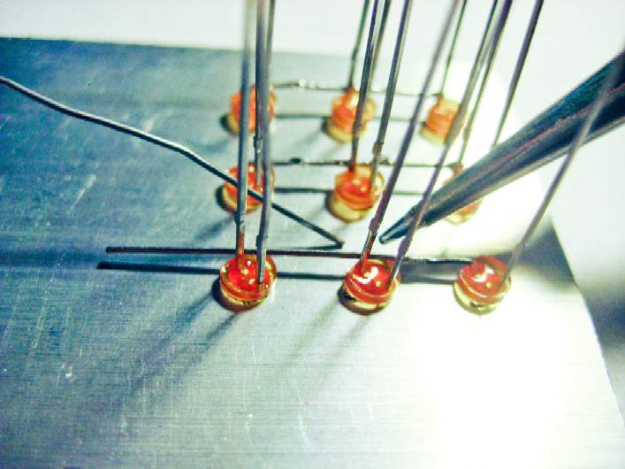
Step 17:
Bend over the "-" lead of the LED shown in the bottom-left corner of the photo.
These next steps in making the plane will be easier, as the LEDs won't rotate in their holes so easily, now that they are soldered to each other.
Please make sure that the "-" lead you just bent over does not touch any of the "+" leads. If you ensured that the LEDs' leads were at 45 degrees to each other in the above steps, then it is much easier to keep the "-" leads from touching any of the "+" leads.
|
|
Solder the fourth "-" lead to the middle "-" lead of this column |
|
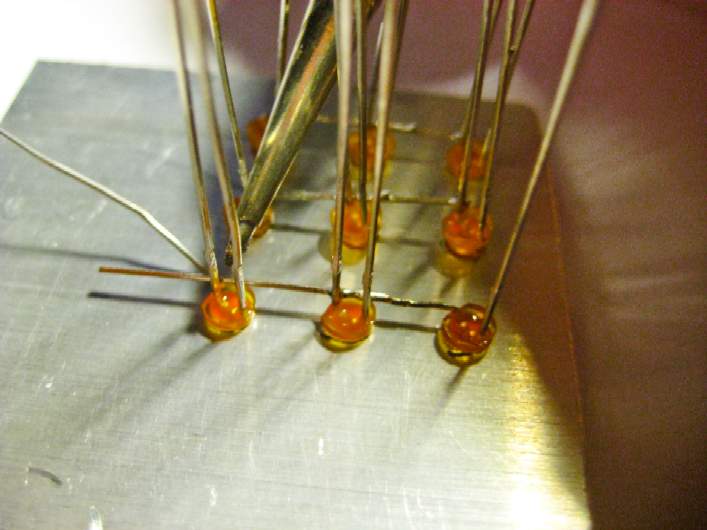
Step 18:
Solder the bent lead to the "-" lead (which is already bent over) of the middle LED of this column at the left of the jig.
|
|
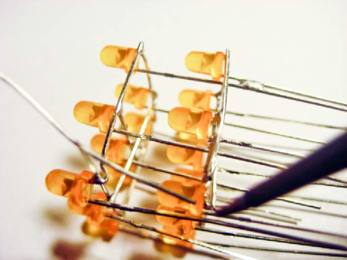
Solder the fourth "-" lead to the top "-" lead of this column |
|
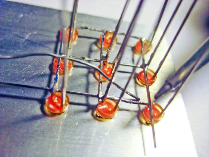
Step 19:
Solder the bent lead to the "-" lead (which is already bent over) of the top LED of this column at the left of the jig.
|
|
Clip the excess "-" lead |
|
Step 20:
Clip the excess lead sticking out from the top of the column, as shown in the photo. Be careful not to snip the "+" lead -- all "+" leads must remain full length, sticking straight up.
|
|
Bend over the fifth lead |
|
Step 21:
Bend down the "-" lead of the middle LED in the top row, as shown in the photo.
Please make sure that the "-" lead you just bent over does not touch any of the "+" leads.
|
|
Solder the fifth "-" lead to the middle "-" lead of this column |
|
Step 22:
Solder the bent lead to the "-" lead (which is still sticking up) of the middle LED of this column in the middle of the jig.
|
|
Solder the fifth "-" lead to the bottom "-" lead of this column |
|
Step 23:
Solder the bent lead to the "-" lead (which is still sticking up) of the bottom LED of this column.
|
|
Clip the excess "-" lead |
|
Step 24:
Clip the excess lead sticking out from the bottom of the column, as shown in the photo. Be careful not to snip the "+" lead -- all "+" leads must remain full length, sticking straight up.
|
|
Bend over the sixth lead |
|
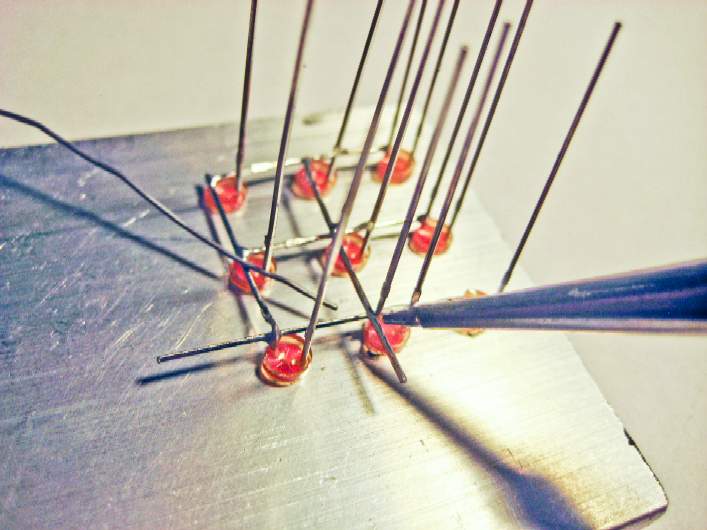
Step 25:
Bend down the "-" lead of the middle LED in the top row, as shown in the photo.
Please make sure that the "-" lead you just bent over does not touch any of the "+" leads.
|
|
Solder the sixth "-" lead to the middle "-" lead of this column |
|
Step 26:
Solder the bent lead to the "-" lead (which is still sticking up) of the middle LED of this column at the right of the jig.
|
|
Solder the sixth "-" lead to the bottom "-" lead of this column |
|
Step 27:
Solder the bent lead to the "-" lead (which is still sticking up) of the bottom LED of this column.
|
|
Clip the excess "-" lead |
|
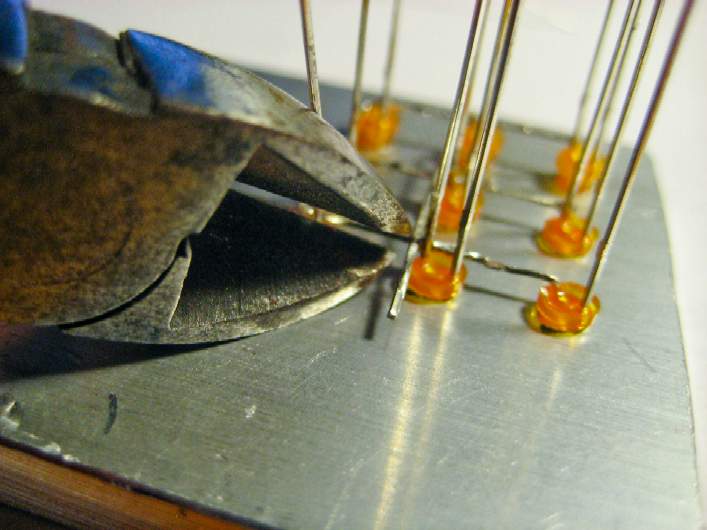
Step 28:
Clip the excess lead sticking out from the bottom of the column, as shown in the photo. Be careful not to snip the "+" lead -- all "+" leads must remain full length, sticking straight up.
|
|
Clip "-" lead of middle LED of bottom row |
|
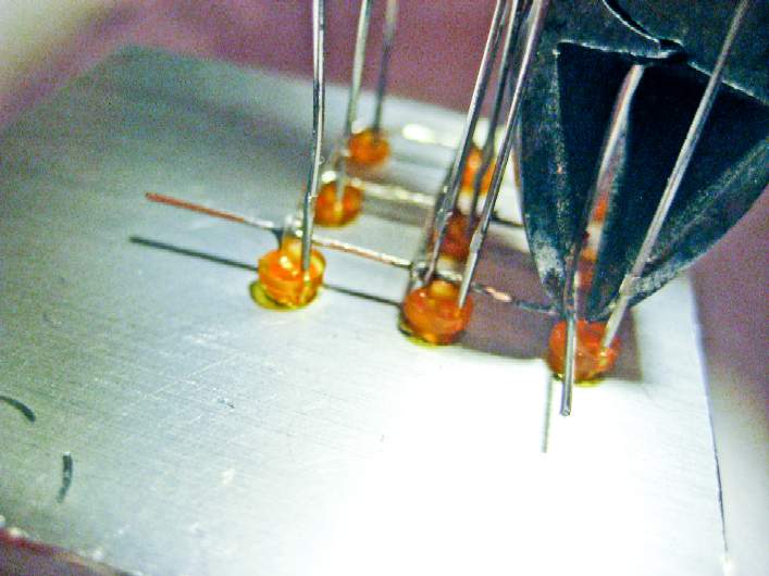
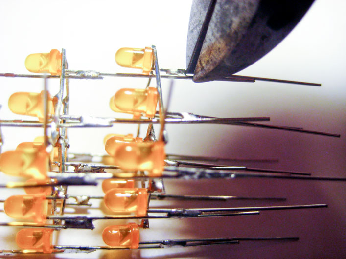
Step 29:
There are still three "-" leads sticking straight up from the jig, and we need to clip them so that only "+" leads are sticking up.
Clip the "-" lead (the short lead!) that is sticking up from the middle LED in the bottom row, as shown in the picture. Be very careful not to cut the "+" lead!
|
|
Clip "-" lead of right LED of middle row |
|
Step 30:
Clip the "-" lead (the short lead!) that is sticking up from the right LED in the middle row, as shown in the picture. Be very careful not to cut the "+" lead!
|
|
Clip "-" lead of middle LED of middle row |
|
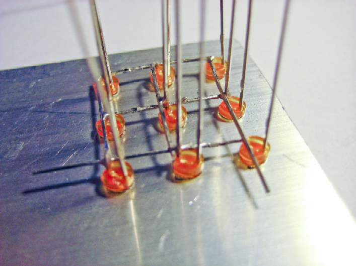
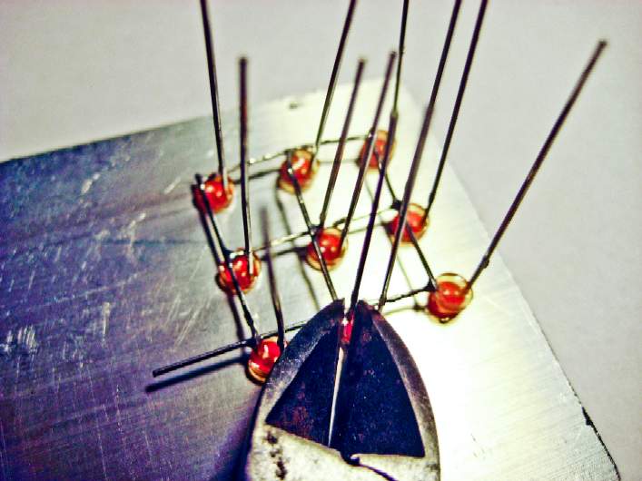
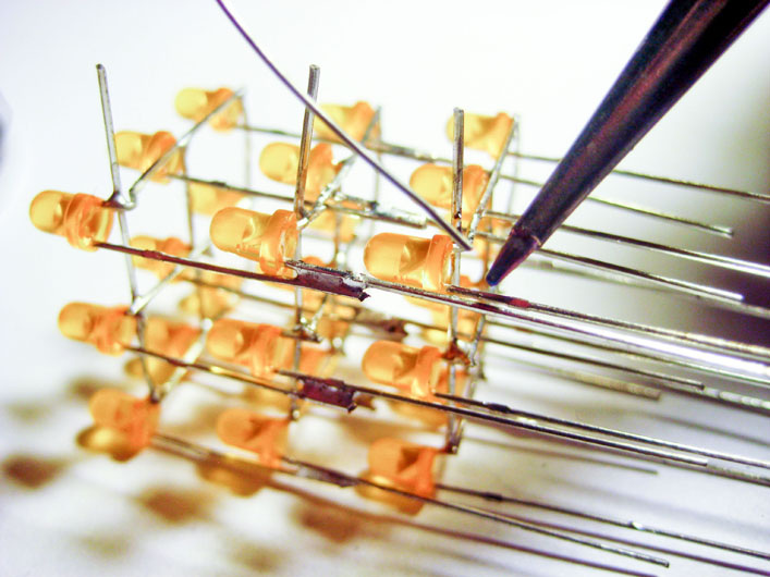
Step 31:
Clip the "-" lead (the short lead!) that is sticking up from the middle LED in the middle row, as shown in the picture. Be very careful not to cut the "+" lead!
|
|
Remove completed plane from the jig
(click for larger image)
|
|
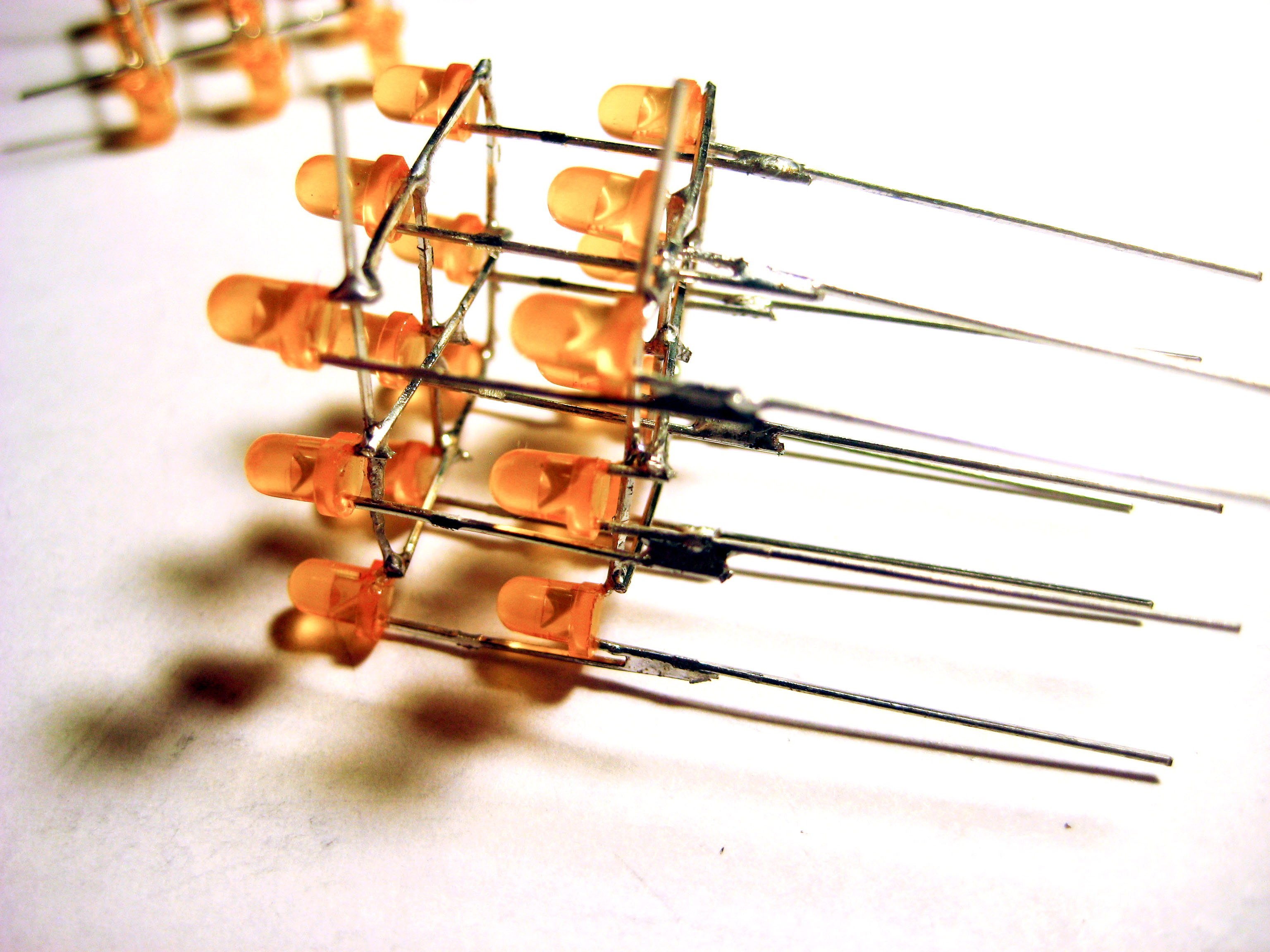
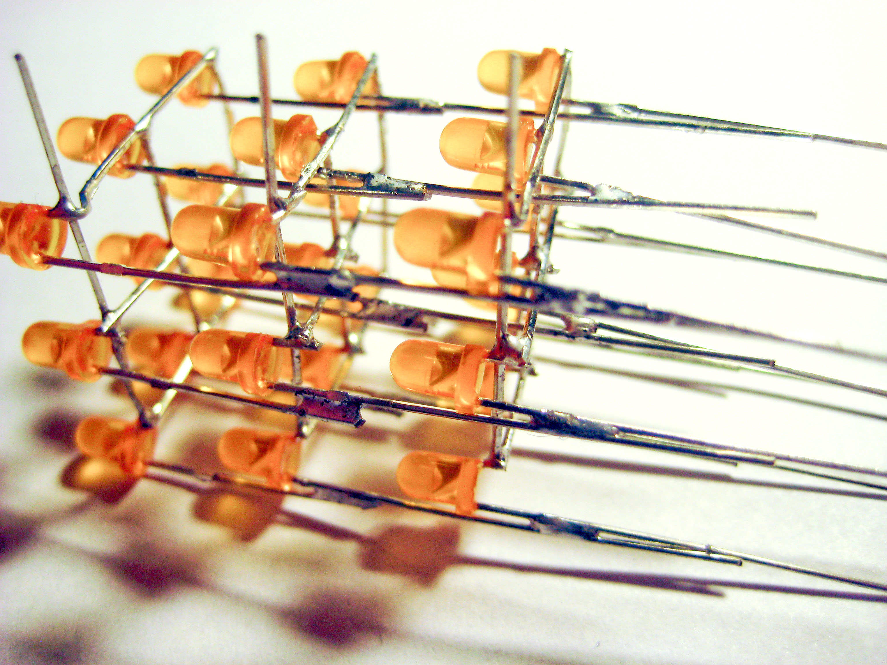
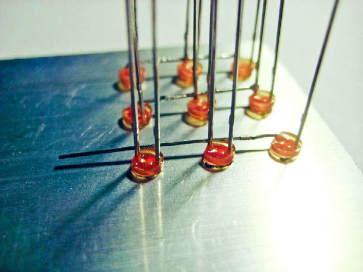
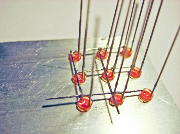
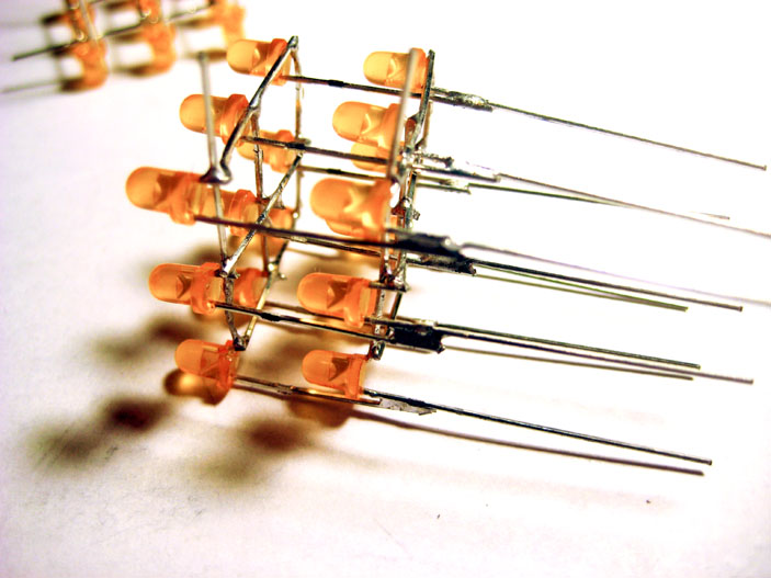
Step 32:
The plane is now complete! Remove it from the jig, and admire it.
See the short stub of a lead sticking out from the lower-left? This will be used to connect this plane's common-cathode to the microcontroller. We will also use it as a physical indicator to align all 3 planes together when we solder the 3 planes into a cube.
|
|
Three completed, identical planes
(click for larger image)
|
|
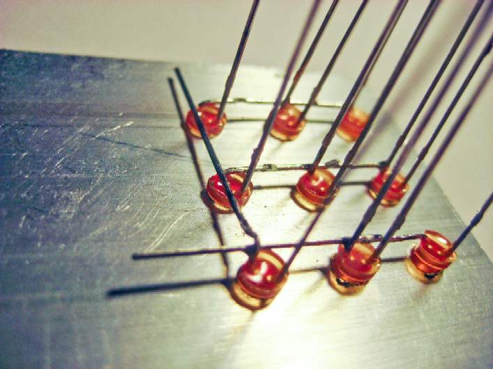
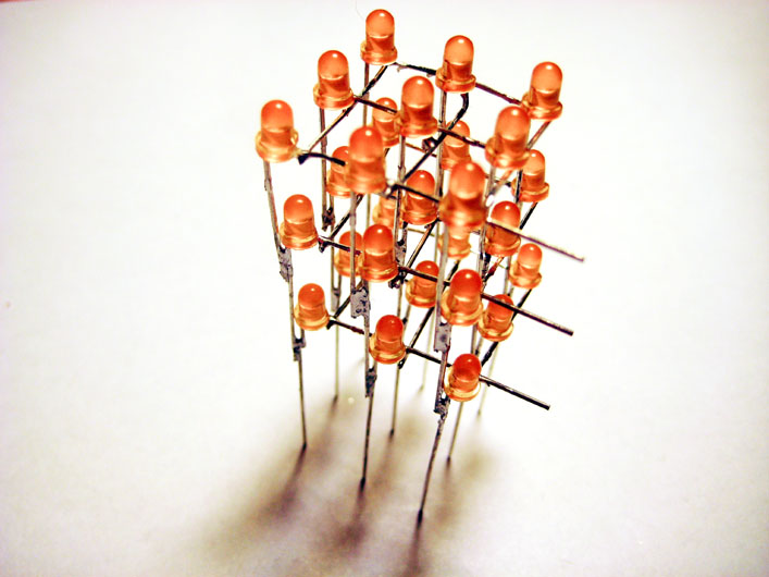
Step 33:
Now make two more planes, each identical to the first one. Repeat steps 5 to 32 to create each plane.
|
|
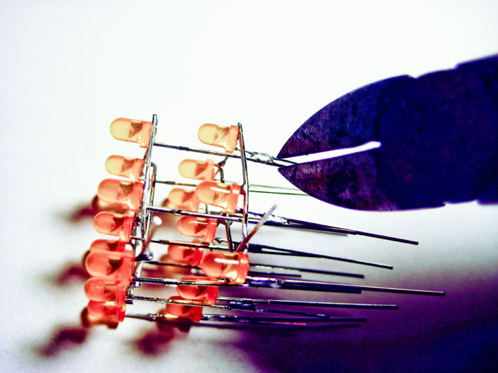
Align all "+" leads for two planes, and solder two "+" leads in one corner
|
|
Step 34:
Now we will solder together a cube from the 3 identical planes that you made. This is done by aligning two planes together (as in the photo on the left), soldering all 9 common-anode columns together, and then aligning the third plane with the other two planes, and adding its 9 "+" leads to the common-anode columns.
First, choose two of the planes. Then, for both planes, straighten all 9 of the "+" leads so that they are all sticking straight up, and so that all 3 "+" leads of each row and each column are all lined up (not crooked).
aDon't solder yet. Let's just orient ourselves first. Remember when you made each plane, and you left a short stub of a lead sticking out one side? With that short common-cathode lead sticking out from both planes in the same direction (pointing up next to my thumb for both planes in the photo), stick the 9 "+" leads from one plane (which will become the top plane of the cube) through the second plane (which will become the middle plane). The 9 "+" leads of the top plane must stick through the second plane so that none of the "+" leads touch any of the "-" leads. The 9 "+" leads of the top plane will be bent to touch the 9 "+" leads of the middle plane in pairs (which will form the cube's columns). All of the pairs of "+" leads must be able to be bent together so that no "+" leads touch any "-" leads.
Now we're ready to start soldering two of the planes together. Hold the top and middle planes in your hand so that the distance between the two planes (in each of the four corners) has a similar distance to the space between two LEDs in a plane.
Now, while continuing to hold the top and middle planes together in your hand, bend together two "+" leads in one corner and solder them together.
|
|
|
While keeping all "+" leads aligned, solder two "+" leads in next corner
|
|
Step 35:
Now solder the two "+" leads together on the next corner.
Then do the same for the other two corners, and then the other 5 columns of "+" leads. I find it easier to solder the LEDs in the middle last.
|
|
Two planes soldered together, with 9 common-anode "+" columns
(click for larger image)
|
|
Step 36:
Here you can see the results of two planes soldered together -- all 9 of the "+" leads are soldered together to make 9 common-anode columns.
|
|
Cut excess "+" column leads on the two planes
|
|
Step 37:
The "+" leads from the top plane are sticking down below the solder connection to the middle plane. Cut these just below the solder connection so that only one lead sticks down on each column.
Be very careful to only cut the excess leads -- we need the long leads from the middle plane to form the common-anode colunmns that will connect to the bottom plane.
|
|
Two planes complete, with excess leads cut
(click for larger image)
|
|
Step 38:
Here is a picture of two planes soldered together with all 9 excess leads of the top plane cut properly.
|
|
Align all "+" leads for all three planes, and solder two "+" leads in one corner
(click for larger image)
|
|
Step 39:
This step is somewhat similar to Step 34, but easier, since the two planes that are now soldered together allowing you to lay the assembly on its side on your table while you solder.
In this step we will be adding the bottom plane of the cube.
Before actually doing any soldering, let's see what we will be doing first. The 9 "+" leads of the middle plane will pass through the second plane. You will make sure that the short common-cathode lead sticking out from this plane sticks out in the same direction as the other two planes (pointing up on all planes in the photo). You will also make sure that that none of the "+" leads touch any of the "-" leads. The 9 "+" leads of the middle plane will be bent to touch the 9 "+" leads of the bottom plane in pairs (which are the cube's columns). All of the pairs of "+" leads must be able to be bent together so that no "+" leads touch any "-" leads.
OK, let's add the bottom plane to finish our cube!
First, grab the bottom plane and straighten all 9 of its "+" leads so that they are all sticking straight up, and so that all 3 "+" leads of each row and each column are all lined up (not crooked).
Time to solder! With the assembly on its side, and laying on the table (as in the photo), slide the bottom plane so that the distance between all three planes (in each of the four corners) has a similar distance to the space between two LEDs in all planes.
Now, bend together two "+" leads in one corner and solder them together.
|
|

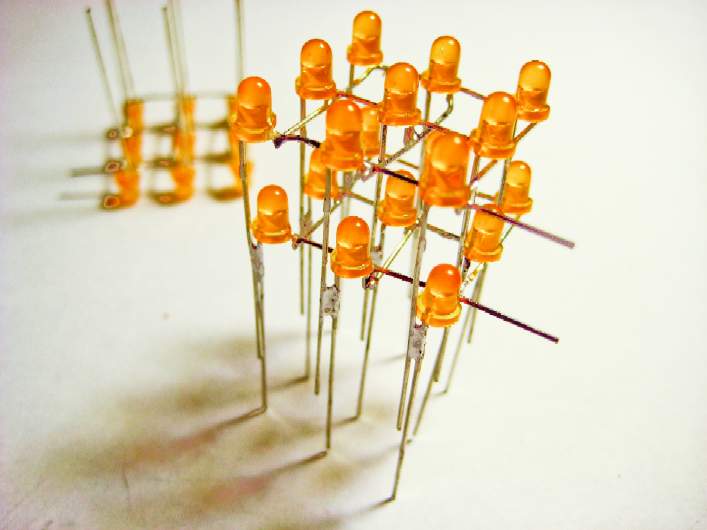
Three planes soldered together, with 9 common-anode "+" columns
(click for larger image)
|
|
Step 40:
This step is similar to Steps 35 and 36.
We'll now solder the two "+" leads together on the next corner, and then do the same for the other two corners, and then the other 5 columns of "+" leads. Again, I find it easier to solder the LEDs in the middle last.
The photo shows all three planes soldered together -- all 9 of the "+" leads are soldered together to make 9 common-anode columns.
|
|
Cut excess "+" column leads on the bottom plane
(click for larger image)
|
|
Step 41:
This step is similar to Step 37, but we'll be cutting the excess leads from the middle plane, instead of from the top plane.
The "+" leads from the middle plane are sticking down below the solder connection to the bottom plane. Cut these just below the solder connection so that only one lead sticks down on each column.
Again, be very careful to only cut the excess leads -- we need the long leads from the bottom plane to form the common-anode colunmns that will solder to the board.
|
|
Completed cube!
(click for larger image)
|
|
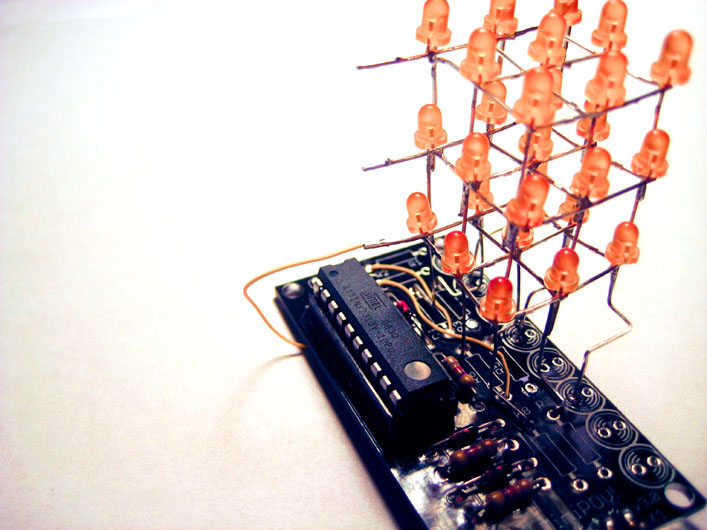
Step 42:
You've now completed the cube!
|
|
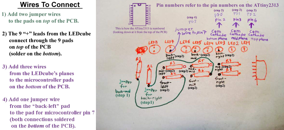
Preview drawing showing wires we'll connect to the PCB
(click for larger image)
|
|
Step 43:
All that remains now is to add a few wires and the cube to the board.
But before actually soldering, let's have a preview of what we'll be doing by taking a look at this drawing.
We'll first add two wires to the top of the PCB, then solder the 9 "+" columns of the cube to the PCB, then add three wires from the "-" planes to the bottom of the PCB, and finally add one more wire to the bottom of the PCB.
|
|
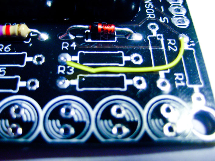
Jumper wire from R1 pad to R4 pad
|
|
Step 44:
See the yellow wire in the photo? It goes from a pad of R1 to a pad of R4. Cut a wire just a little longer than the distance between the two pads shown in the photo. Strip about 1/16" (about 1 or 2 mm) from both ends. Solder them into the pads as shown in the photo.
|
|
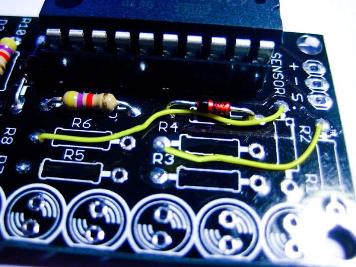
Jumper wire from R2 pad to R6 pad
|
|
Step 45:
For this step cut a wire just a little longer than the distance between the two pads between R2 and R6 shown in the photo. Strip about 1/16" (about 1 or 2 mm) from both ends. Solder them into the pads shown in the photo for R2 and R6.
|
|
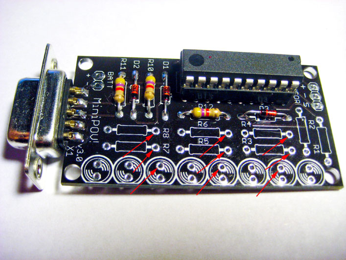
These are the 9 pads where we'll solder in the cube
|
|
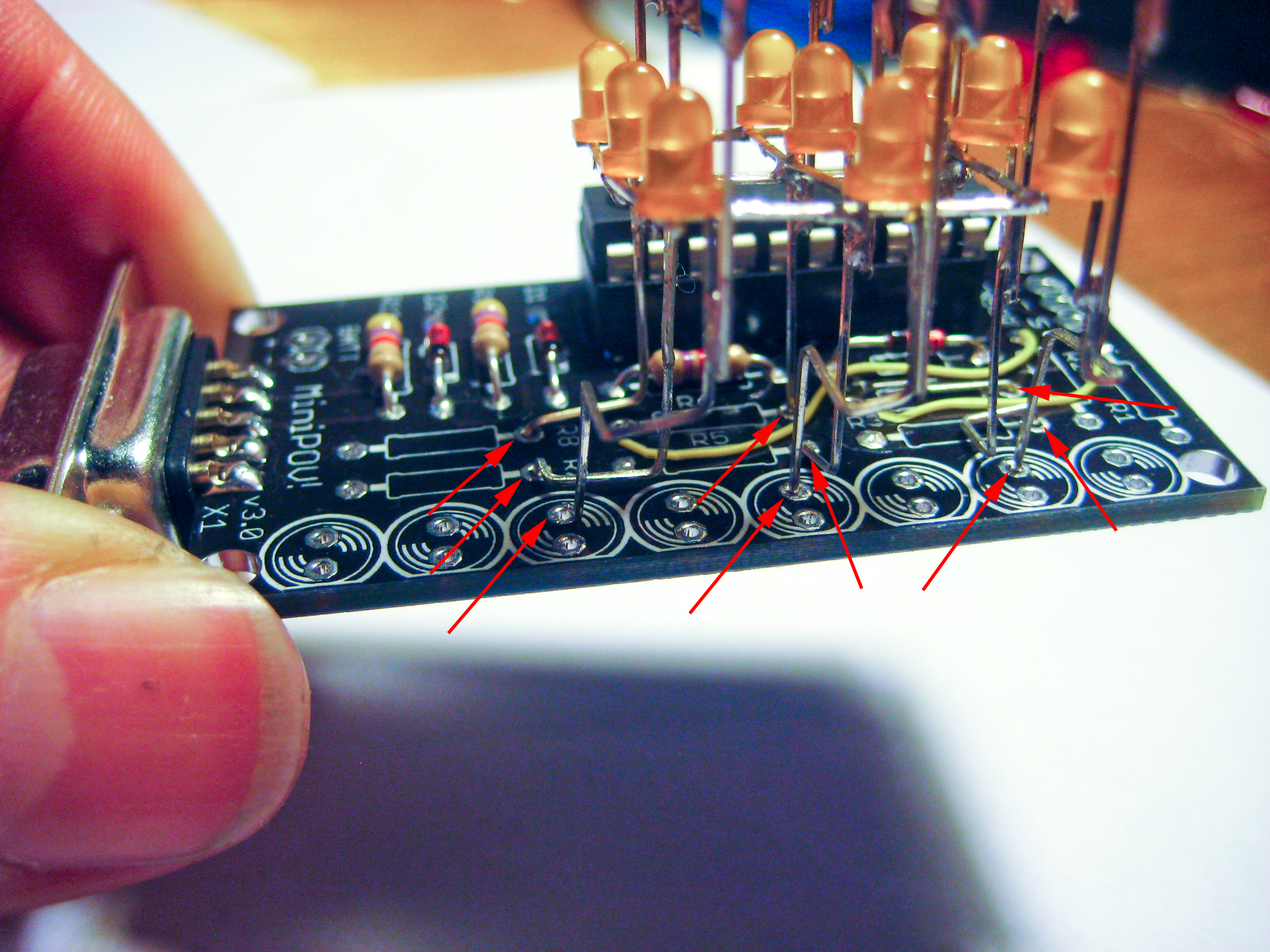
Step 46:
The 9 red arrows in this photo point to the 9 pads where we'll solder in the 9 common-anode "+" column leads into the PCB.
(They are the same pads as shown in the drawing in Step 43.)
|
|

Bent cube leads
(click for larger image)
|
|
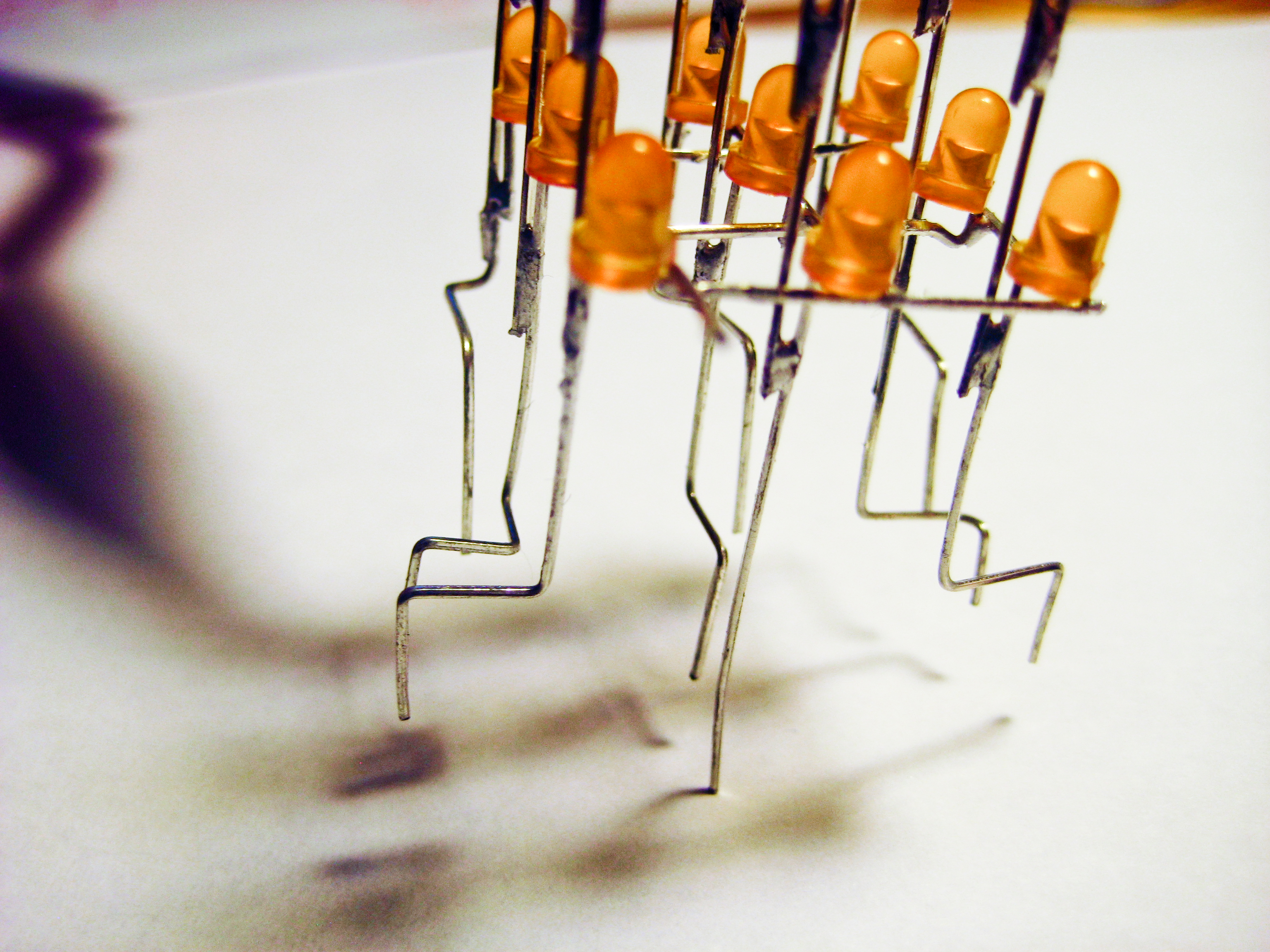
Step 47:
We have to insert the 9 common-anode column leads of the cube into those 9 pads shown in the previous step (Step 46). One way to do this is to bend the 9 leads as shown in this photo. You don't need to be so anal about it, but I think it looks cool this way. The main thing you need to be sure of is that none of these leads touch each other, and they do not touch any metal on the PCB (other than the pads they are to inserted into).
It's not so easy to see in this photo, but note that the little stubs for the common-cathode planes are all pointing out towards you in this photo.
|
|

Bent cube leads inserted into PCB
(click for larger image)
|
|
Step 48:
The 9 red arrows in this photo show the 9 common-anode column leads of the cube inserted into those 9 pads shown in the Step 46.
It's not so easy to see in this photo, but note that the 3 little stubs for the common-cathode planes are all pointing back away from you in this photo (towards the microcontroller).
|
|

Solder all 9 common-anode leads into their pads on the PCB
(click for larger image)
|
|
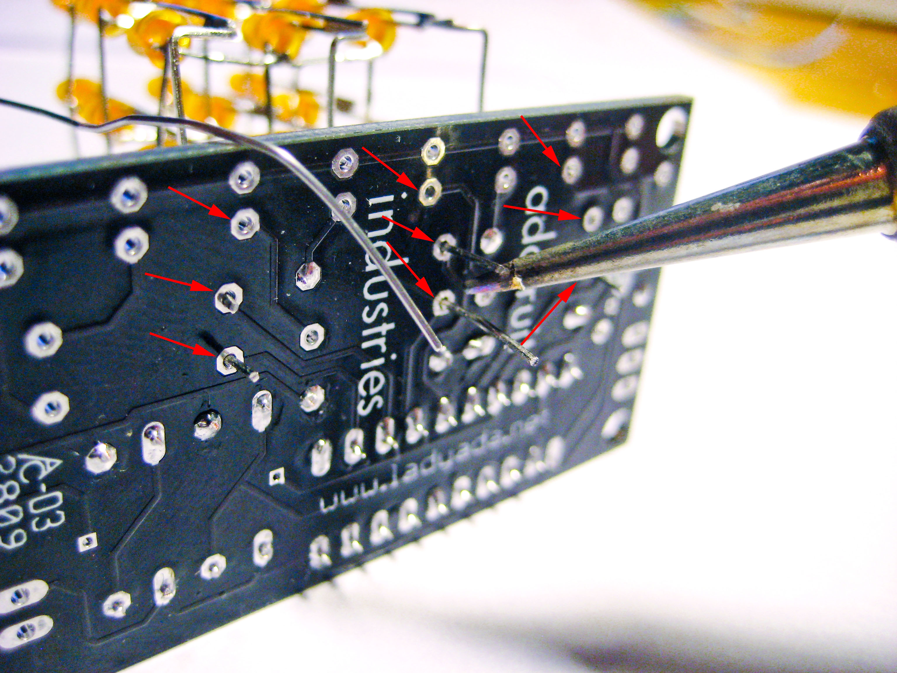
Step 49:
Solder all 9 of the common-anode leads from the cube into their pads on the back of the PCB. The 9 red arrows in this photo show the 9 pads to solder.
|
|
Clip excess cube leads
|
|
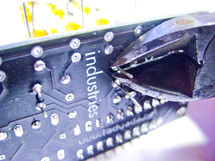
Step 50:
Clip the excess leads from the cube under the PCB. Remember to hold the leads (or cover them) when you cut them (since they have a way of finding eyeballs!).
(They are the same pads as shown in the drawing in Step 43.)
|
|

Alternate view of cube soldered into PCB
(click for larger image)
|
|
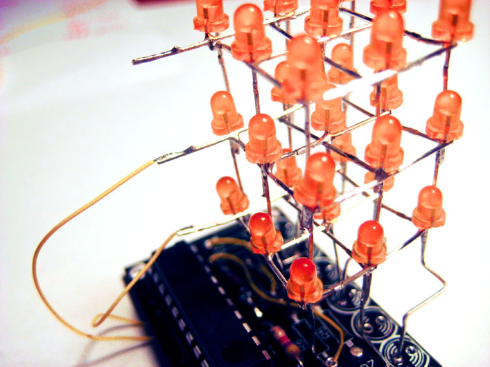
Step 51:
Here is another view of the cube soldered into the PCB.
It is not easy to see in the photo, but the 3 little stubs for each common-cathode plane are pointing out over the microcontroller.
|
|
Solder a jumper for the back-left column
|
|
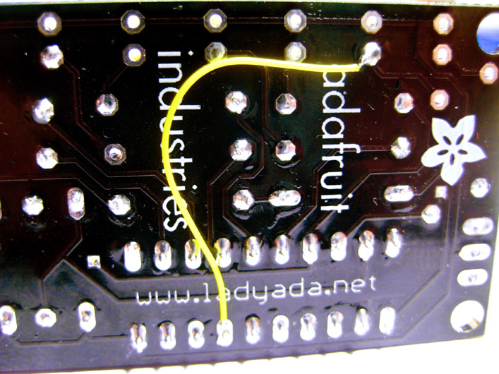
Step 52:
We need to solder a jumper wire onto the bottom of the PCB for the back-left column. The yellow wire in the photo shows where you need to add you jumper -- it goes from the pad for the back-left column of the cube to the pad for pin 7 of the microcontoller.
Cut a wire just a little longer than the distance between the two pads shown in the photo. Strip about 1/16" (about 1 or 2 mm) from both ends. Solder them into the pads as shown in the photo.
|
|
Tin the little stub for the Bottom Plane
|
|
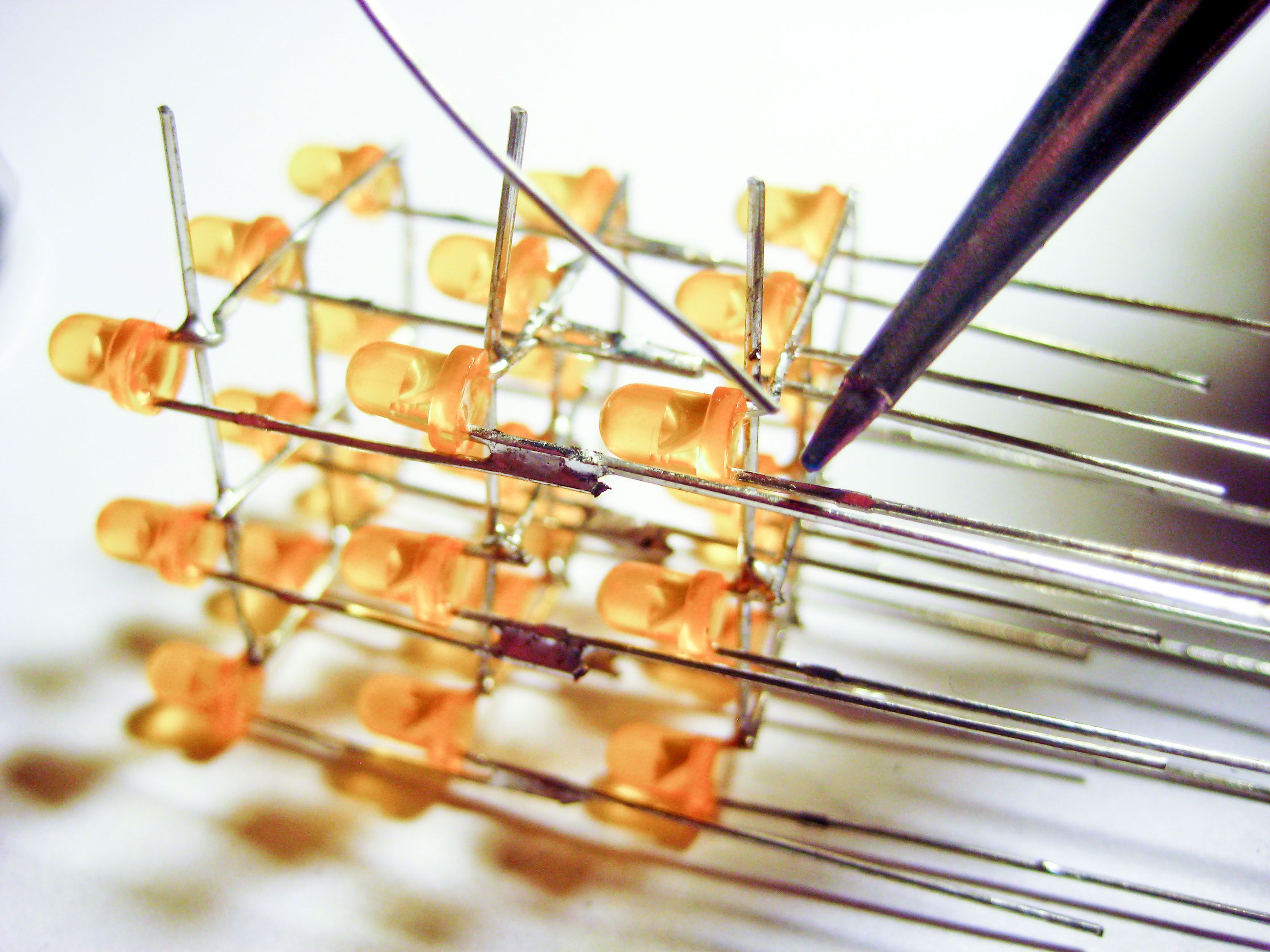
Step 53:
We are now going to solder a wire from the little stub for the Bottom Plane to the pad (under the PCB) for pin 2. To prepare for this, tin the little stub for the Bottom Plane.
To tin the little stub, heat up the end of it by holding a cleaned solder iron tip against it for about 1 second, and then add solder to coat it with a thin layer of solder.
|
|
Wire from little stub for Bottom Plane to pin 2 of microcontroller
|
|
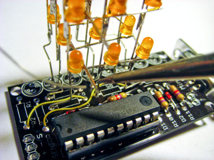
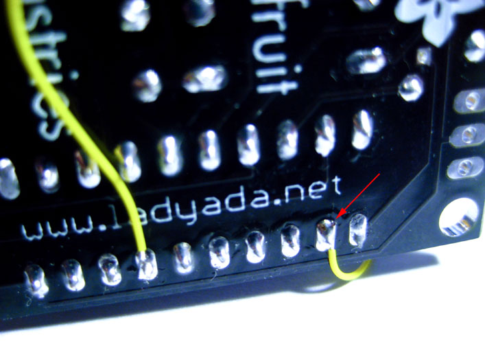
Step 54:
Cut a wire just a little longer than the distance between the little stub for the Bottom Plane and the pad shown in the photo (with the red arrow).
Strip about 1/16" (about 1 or 2 mm) from both ends of the wire.
Solder one end to the tinned little stub for the Bottom Plane.
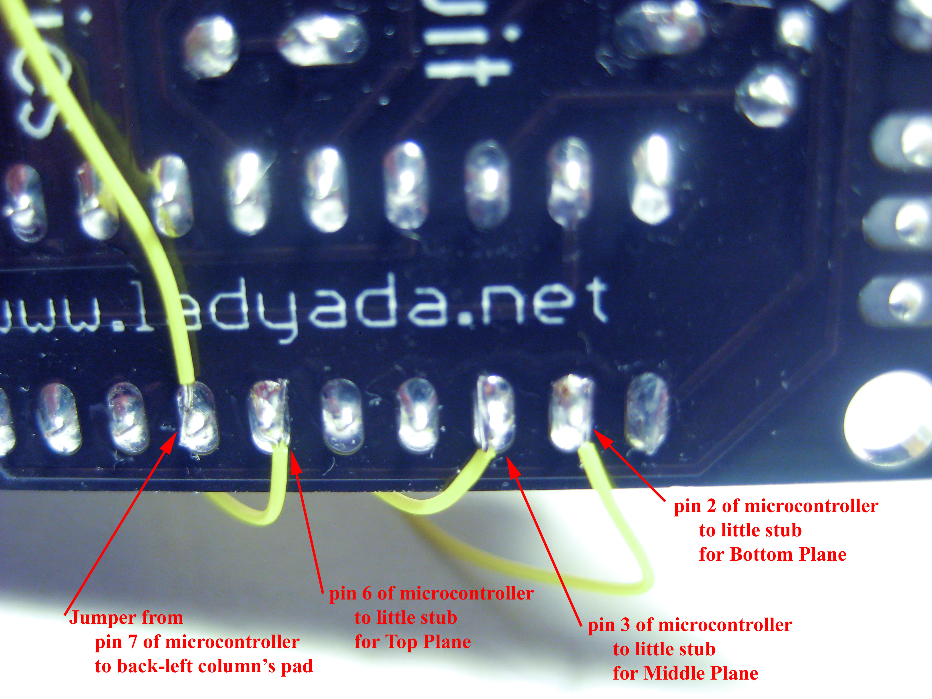
Solder the other end to the pad shown in the photo (with the red arrow). This is pin 2 of the microcontroller.
|
|
Wire soldered to little stub for Bottom Plane
|
|
Step 55:
This photo shows the other end of the wire soldered to the little stub for the Bottom Plane.
|
|
Wire soldered to little stub for Middle Plane
|
|
Step 56:
We are now going to solder a wire from the little stub for the Middle Plane to the pad (under the PCB) for pin 3 of the microcontroller. To prepare for this, tin the little stub for the Middle Plane.
Cut a wire just a little longer than the distance between the little stub for the Middle Plane and the pad for pin 3 of the microcontroller.
Strip about 1/16" (about 1 or 2 mm) from both ends of the wire.
Solder one end to the tinned little stub for the Middle Plane.
Solder the other end to the pad (on the bottom of the PCB) for pin 3 of the microcontroller.
|
|
3 wires soldered to all 3 little stubs for for the 3 planes
(click for larger image)
|
|
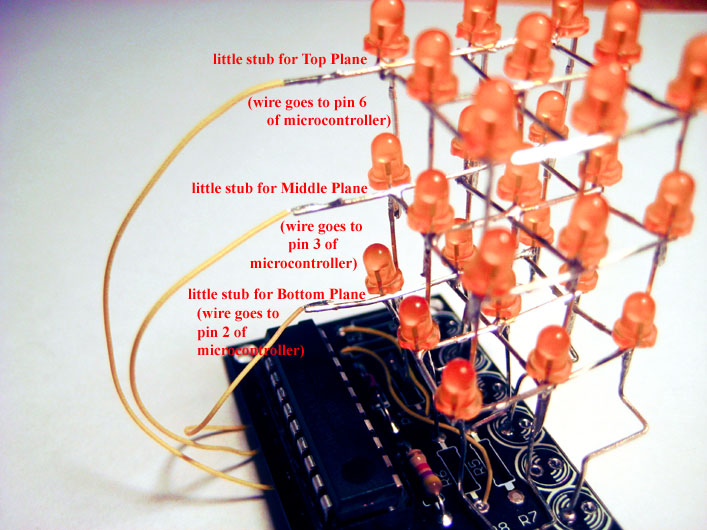
Step 57:
Finally, one last wire! We are now going to solder a wire from the little stub for the Top plane to the pad (under the PCB) for pin 6 of the microcontroller. To prepare for this, tin the little stub for the Top Plane.
Cut a wire just a little longer than the distance between the little stub for the Top Plane and the pad for pin 6 of the microcontroller.
Strip about 1/16" (about 1 or 2 mm) from both ends of the wire.
Solder one end to the tinned little stub for the Top Plane.
Solder the other end to the pad (on the bottom of the PCB) for pin 6 of the microcontroller.
The photo shows all 3 little stubs for all 3 planes with wires connected.
|
|
4 wires soldered to 4 microcontroller pins
(click for larger image)
|
|
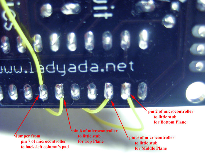
Step 58:
This photo shows the 4 pads of the microcontroller that we soldered wires to.
|
|
Shorten battery wires
|
|
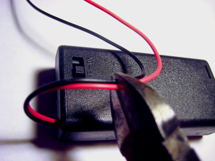
Step 59:
Your finished LEDcube will look nicer if you shorten the wires to the battery pack. Cut them to about 1.5" (about 4cm).
|
|
Solder battery wires
|
|
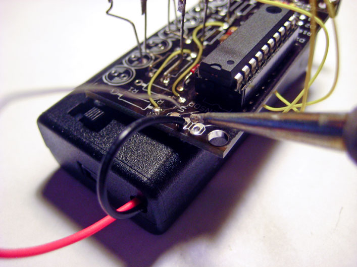
Step 60:
Strip about 1/8" (about 3mm) of insulation off of each battery wire.
Solder the black wire to the pad marked "-".
Solder the red wire to the pad marked "+".
|
|

Completed LEDcube
(click for larger image)
|
|
Step 61:
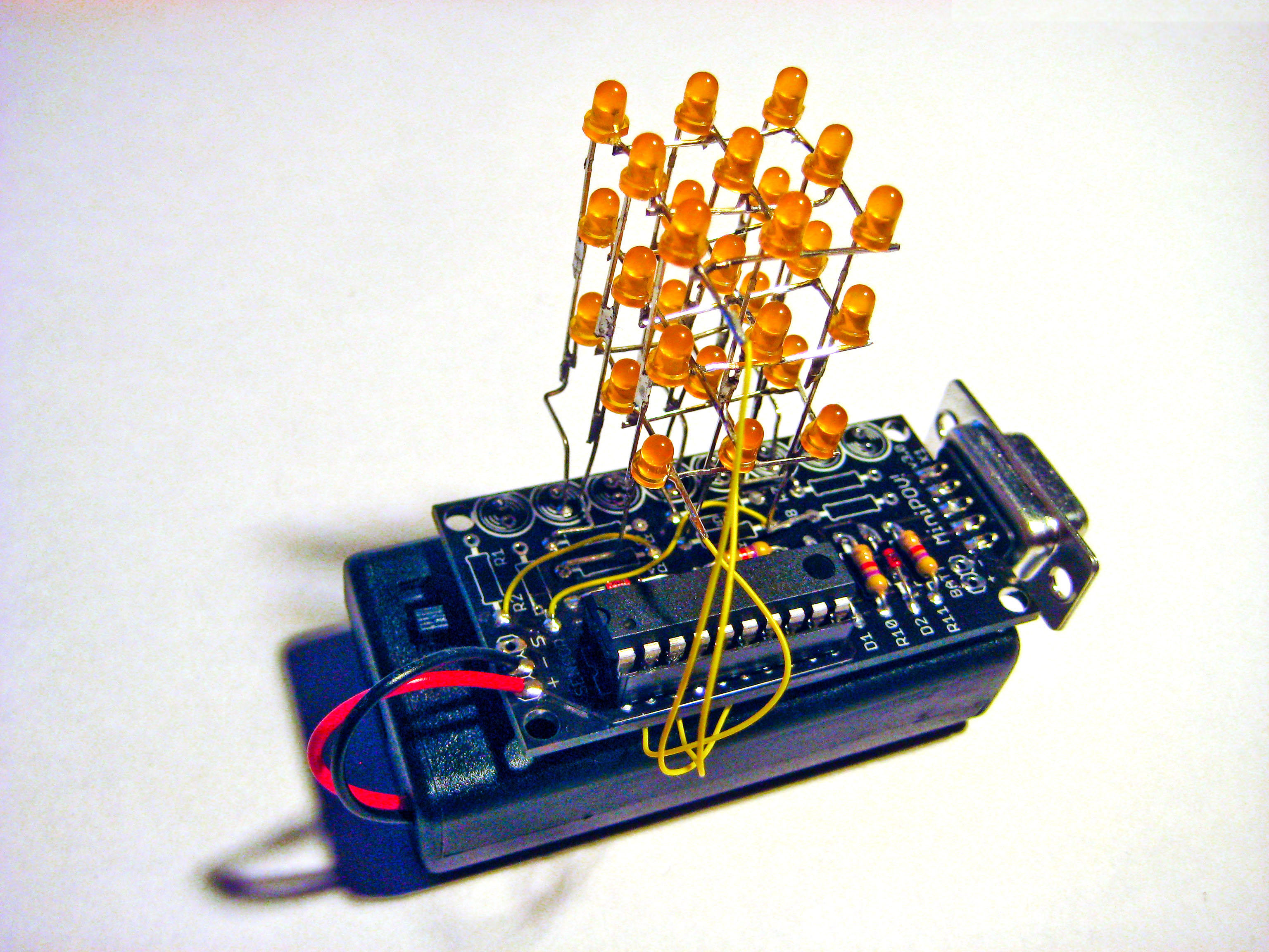
With the power switch OFF, place two AA batteries in the battery pack.
If you bought an LEDcube kit, the microcontroller comes pre-programmed with a test sequence. Once you turn on the power you will see the test sequence: each of the 27 LEDs light up, one at a time.
If each LED does not light up, then debug:
- batteries in correctly?
- solder connections good?
- on the cube, are there any "+" wires touching any "-" wires?
Once the LEDcube is working correctly, you can use hot glue to connect the PCB to the battery pack (make sure the power switch is facing up, as in the photo).
|
|
Program your LEDcube
|
|
Step 62:
The
test firmware
is kinda cool, but you can
download
the firmware (and the
makefile)
and program the much more interesting
LEDcube firmware!
To program the LEDcube firmware, use a command (or terminal) window, and change the directory to the place where you downloaded the firmware and makefile. Then type in the following command:
make program-ledcube
If things go well you will see three lines of ####### characters, followed by the words "thank you".
For more details on how to program, please see the
Ladyada website programming page for the MiniPOV3 kit.
Once you can successfully program your LEDcube, try hacking my firmware and programming in your own animation sequence!
|
|
|